LM317P STMicroelectronics, LM317P Datasheet
LM317P
Specifications of LM317P
LM317P
Available stocks


Related parts for LM317P


LM317P Summary of contents
Page 1
... Table 1. Device summary TO-220 D²PAK (tape and reel) LM217T LM317T November 2010 1 adjustable voltage regulators Order codes TO-220FP LM217D2T-TR LM317D2T-TR LM317P Doc ID 2154 Rev 16 LM117 LM217, LM317 TO-220 TO-220FP D²PAK TO-3 TO-3 LM117K LM217K LM317K 1/25 www ...
Page 2
Contents Contents 1 Pin configuration . . . . . . . . . . . . . . . . . . . . . . . . . . . . . . . . . . . ...
Page 3
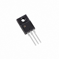
LM117, LM217, LM317 1 Pin configuration Figure 1. Pin connections (top view) TO-220 D²PAK (Any Type) Doc ID 2154 Rev 16 Pin configuration TO-220FP TO-3 3/25 ...
Page 4
Maximum ratings 2 Maximum ratings Table 2. Absolute maximum ratings Symbol Input-reference differential voltage Output current O T Operating junction temperature for Power dissipation D T Storage temperature STG Note: Absolute maximum ...
Page 5
LM117, LM217, LM317 3 Diagram Figure 2. Schematic diagram Doc ID 2154 Rev 16 Diagram 5/25 ...
Page 6
Electrical characteristics 4 Electrical characteristics 500 mA 150 °C for LM217, unless otherwise specified. J Table 4. Electrical characteristics for LM117/LM217 Symbol Parameter ...
Page 7
LM117, LM217, LM317 500 mA specified. Table 5. Electrical characteristics for LM317 Symbol Parameter ΔV Line regulation O ΔV Load regulation O I Adjustment pin current ADJ ΔI ...
Page 8
Typical characteristics 5 Typical characteristics Figure 3. Output current vs. input-output differential voltage Figure 5. Reference voltage vs. junction Figure 6. Basic adjustable regulator 8/25 Figure 4. Dropout voltage vs. junction temperature Doc ID 2154 Rev 16 LM117, LM217, LM317 ...
Page 9
LM117, LM217, LM317 6 Application information The LM117, LM217, LM317 provides an internal reference voltage of 1.25 V between the output and adjustments terminals. This is used to set a constant current flow across an external resistor divider (see V ...
Page 10
Application information Figure 8. Slow turn- regulator Figure 9. Current regulator REF 1 Figure 10 electronic shut-down regulator 10/ ADJ 1 Doc ...
Page 11
LM117, LM217, LM317 Figure 11. Digitally selected outputs (R sets maximum V 2 Figure 12. Battery charger ( sets output impedance of charger Z S charged battery Use ...
Page 12
Application information Figure 13. Current limited 6 V charger * R3 sets peak current (0.6 A for 1 0 recommended to filter out input transients. 12/25 Doc ID 2154 Rev 16 LM117, LM217, LM317 ...
Page 13
LM117, LM217, LM317 7 Package mechanical data In order to meet environmental requirements, ST offers these devices in different grades of ® ECOPACK packages, depending on their level of environmental compliance. ECOPACK specifications, grade definitions and product status are available ...
Page 14
Package mechanical data Figure 14. Drawing dimension TO-220 (type STD-ST Dual Gauge) Note: 1 Max resin gate protrusion: 0.5 mm. 2 Resin gate position is accepted in each of the two positions shown on the drawing, or their symmetrical. 14/25 ...
Page 15
LM117, LM217, LM317 Figure 15. Drawing dimension TO-220 (type STD-ST Single Gauge) Note: In spite of some difference in tolerances, the packages are compatible. Doc ID 2154 Rev 16 Package mechanical data 8174627_B 15/25 ...
Page 16
Package mechanical data Figure 16. Drawing dimension tube for TO-220 Dual Gauge (mm.) Figure 17. Drawing dimension tube for TO-220 Single Gauge (mm.) 16/25 Doc ID 2154 Rev 16 LM117, LM217, LM317 ...
Page 17
LM117, LM217, LM317 Dim. Min 0. 3. TO-3 mechanical data mm. Typ. Max. 11.85 1.05 1.10 1.70 8.7 20.0 10.9 16.9 26.2 4.09 39.5 30. Doc ...
Page 18
Package mechanical data Dim. Min. A 4.40 B 2.5 D 2.5 E 0.45 F 0.75 F1 1.15 F2 1.15 G 4.95 G1 2 28.6 L4 9.8 L5 2 DIA. 3 18/25 TO-220FP ...
Page 19
LM117, LM217, LM317 Figure 18. Drawing dimension D²PAK (type STD-ST) Doc ID 2154 Rev 16 Package mechanical data 0079457/L 19/25 ...
Page 20
Package mechanical data Figure 19. Drawing dimension D²PAK (type WOOSEOK-SUBCON.) 20/25 Doc ID 2154 Rev 16 LM117, LM217, LM317 0079457/L ...
Page 21
LM117, LM217, LM317 Table 7. D²PAK mechanical data Dim. MIN. A 4.40 A1 0.03 b 0.70 b2 1.14 c 0.45 c2 1.23 D 8. 2.49 L 2.29 L1 ...
Page 22
Package mechanical data Figure 20. D²PAK footprint recommended data Table 8. Footprint data Dim 22/25 Values mm. 12.20 9.75 16.90 3.50 1.60 2.54 5.08 Doc ID 2154 Rev 16 LM117, LM217, LM317 inch. ...
Page 23
LM117, LM217, LM317 2 Tape & reel D PAK-P Dim. Min 12 10.50 Bo 15.70 Ko 4.80 Po 3 PAK-D PAK/A-P PAK/A mechanical data mm. Typ. Max. ...
Page 24
Revision history 8 Revision history Table 9. Document revision history Date Revision 01-Sep-2004 10 19-Jan-2007 11 13-Jun-2007 12 23-Nov-2007 13 06-Feb-2008 14 02-Mar-2010 15 17-Nov-2010 16 24/25 Mistake V ==> tables 1, 4 and 5. REF O D²PAK ...
Page 25
... LM117, LM217, LM317 Information in this document is provided solely in connection with ST products. STMicroelectronics NV and its subsidiaries (“ST”) reserve the right to make changes, corrections, modifications or improvements, to this document, and the products and services described herein at any time, without notice. All ST products are sold pursuant to ST’s terms and conditions of sale. ...