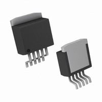
LP3856ES-ADJ/NOPB National Semiconductor, LP3856ES-ADJ/NOPB Datasheet - Page 10

LP3856ES-ADJ/NOPB
Manufacturer Part Number
LP3856ES-ADJ/NOPB
Description
IC REG LDO 3A ADJ VOLT TO-263-5
Manufacturer
National Semiconductor
Datasheet
1.LP3856ES-ADJNOPB.pdf
(16 pages)
Specifications of LP3856ES-ADJ/NOPB
Regulator Topology
Positive Adjustable
Voltage - Output
Adjustable
Voltage - Input
2.5 ~ 7 V
Voltage - Dropout (typical)
0.39V @ 3A
Number Of Regulators
1
Current - Output
3A (Max)
Operating Temperature
-40°C ~ 125°C
Mounting Type
Surface Mount
Package / Case
TO-263-5, D²Pak (5 leads + Tab), TO-263BA
Primary Input Voltage
7V
Dropout Voltage Vdo
390mV
No. Of Pins
5
Output Current
3A
Operating Temperature Range
-40°C To +125°C
Msl
MSL 3 - 168 Hours
Filter Terminals
SMD
Rohs Compliant
Yes
Lead Free Status / RoHS Status
Lead free / RoHS Compliant
Current - Limit (min)
-
Other names
*LP3856ES-ADJ
*LP3856ES-ADJ/NOPB
LP3856ES-ADJ
*LP3856ES-ADJ/NOPB
LP3856ES-ADJ
www.national.com
Application Hints
SETTING THE OUTPUT VOLTAGE
The output voltage is set using the resistors R1 and R2 (see
Typical Application Circuit). The output is also dependent on
the reference voltage (typically 1.216V) which is measured at
the ADJ pin. The output voltage is given by the equation:
This equation does not include errors due to the bias current
flowing in the ADJ pin which is typically about 10 nA. This error
term is negligible for most applications. If R1 is > 100kΩ , a
small error may be introduced by the ADJ bias current.
The tolerance of the external resistors used contributes a sig-
nificant error to the output voltage accuracy, with 1% resistors
typically adding a total error of approximately 1.4% to the out-
put voltage (this error is in addition to the tolerance of the
reference voltage at V
TURN-ON CHARACTERISTICS FOR OUTPUT VOLTAGES
PROGRAMMED TO 2.0V OR BELOW
As Vin increases during start-up, the regulator output will track
the input until Vin reaches the minimum operating voltage
(typically about 2.2V). For output voltages programmed to
2.0V or below, the regulator output may momentarily exceed
its programmed output voltage during start up. Outputs pro-
grammed to voltages above 2.0V are not affected by this
behavior.
EXTERNAL CAPACITORS
Like any low-dropout regulator, external capacitors are re-
quired to assure stability. these capacitors must be correctly
selected for proper performance.
INPUT CAPACITOR: An input capacitor of at least 10µF is
required. Ceramic or Tantalum may be used, and capacitance
may be increased without limit
OUTPUT CAPACITOR: An output capacitor is required for
loop stability. It must be located less than 1 cm from the device
and connected directly to the output and ground pins using
traces which have no other currents flowing through them
(see PCB Layout section).
The minimum amount of output capacitance that can be used
for stable operation is 10µF. For general usage across all load
currents and operating conditions, the part was characterized
using a 10µF Tantalum input capacitor. The minimum and
maximum stable ESR range for the output capacitor was then
measured which kept the device stable, assuming any output
capacitor whose value is greater than 10µF (see
low).
V
OUT
= V
ADJ
ADJ
).
x ( 1 + R1 / R2)
Figure 1
be-
10
FIGURE 1. ESR Curve for C
It should be noted that it is possible to operate the part with
an output capacitor whose ESR is below these limits, assum-
ing that sufficient ceramic input capacitance is provided. This
will allow stable operation using ceramic output capacitors
(see next section).
OPERATION WITH CERAMIC OUTPUT CAPACITORS
LP385X voltage regulators can operate with ceramic output
capacitors if the values of input and output capacitors are se-
lected appropriately. The total ceramic output capacitance
must be equal to or less than a specified maximum value in
order for the regulator to remain stable over all operating con-
ditions. This maximum amount of ceramic output capacitance
is dependent upon the amount of ceramic input capacitance
used as well as the load current of the application. This rela-
tionship is shown in
stable value of ceramic output capacitance as a function of
ceramic input capacitance for load currents of 1A, 2A, and 3A.
For example, if the maximum load current is 1A, a 10µF ce-
ramic input capacitor will allow stable operation for values of
ceramic output capacitance from 10µF up to about 500µF.
FIGURE 2. Maximum Ceramic Output Capacitance vs
Ceramic Input Capacitance
Figure
Capacitor)
OUT
2, which graphs the maximum
(with 10µF Tantalum Input
20074295
20074270


