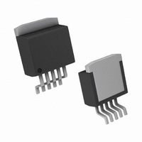
LP3856ES-2.5/NOPB National Semiconductor, LP3856ES-2.5/NOPB Datasheet

LP3856ES-2.5/NOPB
Specifications of LP3856ES-2.5/NOPB
*LP3856ES-2.5/NOPB
LP3856ES-2.5
Related parts for LP3856ES-2.5/NOPB
LP3856ES-2.5/NOPB Summary of contents
Page 1
... Typical Application Circuits **SD and ERROR pins must be pulled high through a 10kΩ pull-up resistor. Connect the ERROR pin to ground if this function is not used. See Application Hints for more information. © 2011 National Semiconductor Corporation LP3853/LP3856 Features ■ ...
Page 2
See Application Hints for more information. Connection Diagrams Top View TO220-5 Package Bent, Staggered Leads Pin Description for TO220-5 and TO263-5 Packages Pin # Name ...
Page 3
... LP3853ES-2.5 Rail LP3853ES-2.5 Tape and Reel LP3853ES-1.8 Rail LP3853ES-1.8 Tape and Reel LP3856ES-5.0 Rail LP3856ES-5.0 Tape and Reel LP3856ES-3.3 Rail LP3856ES-3.3 Tape and Reel LP3856ES-2.5 Rail LP3856ES-2.5 Tape and Reel LP3856ES-1.8 Rail LP3856ES-1.8 Tape and Reel LP3853ET-5.0 Rail LP3853ET-3.3 Rail LP3853ET-2.5 Rail LP3853ET-1 ...
Page 4
Block Diagrams www.national.com LP3853 20030903 LP3856 20030929 4 ...
Page 5
... Absolute Maximum Ratings If Military/Aerospace specified devices are required, please contact the National Semiconductor Sales Office/ Distributors for availability and specifications. Storage Temperature Range Lead Temperature (Soldering, 5 sec.) ESD Rating (Note 3) Power Dissipation (Note 2) Input Supply Voltage (Survival) Shutdown Input Voltage (Survival) ...
Page 6
Symbol Parameter Shutdown Input V Shutdown Threshold SDT T Turn-off delay dOFF T Turn-on delay dON I SD Input Current SD Error Flag V Threshold T V Threshold Hysteresis TH V Error Flag Saturation EF(Sat) Td Flag Reset Delay I ...
Page 7
Typical Performance Characteristics C = 10µF, S/D pin is tied OUT Dropout Voltage vs Output Load Current Ground Current vs Output Voltage Errorflag Threshold vs Junction Temperature Unless otherwise specified: T ...
Page 8
DC Line Regulation vs Temperature Noise vs Frequency Load Transient Response 100µF, OSCON IN OUT www.national.com 20030959 Load Transient Response 20030961 Load Transient Response ...
Page 9
Load Transient Response 10µF, TANTALUM IN OUT 20030974 Load Transient Response 10µF, OSCON IN OUT 20030976 Load Transient Response 100µF, POSCAP IN OUT 20030978 Load Transient Response C ...
Page 10
Load Transient Response 100µF, TANTALUM IN OUT Load Transient Response 10µF CERAMIC 10µF CERAMIC OUT Load Transient Response 10µF CERAMIC ...
Page 11
Application Hints EXTERNAL CAPACITORS Like any low-dropout regulator, external capacitors are re- quired to assure stability. These capacitors must be correctly selected for proper performance. INPUT CAPACITOR: An input capacitor of at least 10µF is required. Ceramic or Tantalum may ...
Page 12
The Z5U and Y5V also exhibit a severe temperature effect, losing more than 50% of nominal capac- itance at high and low limits of the temperature range. X7R and X5R dielectric ceramic capacitors are strongly rec- ...
Page 13
Increasing the area will decrease the chance of fitting the die into a smaller package. Increasing the current drawn by the internal reference increases the total supply current (ground pin current). Using an optimized trade-off of ground pin current ...
Page 14
FIGURE 4. Improving remote load regulation using LP3856 SHUTDOWN OPERATION A CMOS Logic low level signal at the Shutdown (SD) pin will turn-off the regulator. Pin SD must be actively terminated through a 10kΩ pull-up resistor for a proper operation. ...
Page 15
FIGURE 5. θ vs Copper (1 Ounce) Area for TO-263 JA package As shown in the figure, increasing the copper area beyond 1 square inch produces very little improvement. The minimum value for θ for the TO-263 package mounted to ...
Page 16
Physical Dimensions TO220 5-lead, Molded, Stagger Bend Package (TO220-5) For Order Numbers, refer to the “Ordering Information” section of this document. www.national.com inches (millimeters) unless otherwise noted NS Package Number T05D 16 ...
Page 17
TO263 5-Lead, Molded, Surface Mount Package (TO263-5) NS Package Number TS5B For Order Numbers, refer to the “Ordering Information” section of this document. 17 www.national.com ...
Page 18
... For more National Semiconductor product information and proven design tools, visit the following Web sites at: www.national.com Products Amplifiers www.national.com/amplifiers Audio www.national.com/audio Clock and Timing www.national.com/timing Data Converters www.national.com/adc Interface www.national.com/interface LVDS www.national.com/lvds Power Management www.national.com/power Switching Regulators www.national.com/switchers LDOs www.national.com/ldo LED Lighting www ...


