BA15T Rohm Semiconductor, BA15T Datasheet - Page 8
BA15T
Manufacturer Part Number
BA15T
Description
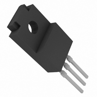
IC REGULATOR 15V 1A TO220FP
Manufacturer
Rohm Semiconductor
Datasheet
1.BA06FP-E2.pdf
(9 pages)
Specifications of BA15T
Regulator Topology
Positive Fixed
Voltage - Output
15V
Voltage - Input
Up to 25V
Voltage - Dropout (typical)
0.3V @ 500mA
Number Of Regulators
1
Current - Output
1A (Max)
Operating Temperature
0°C ~ 125°C
Mounting Type
Through Hole
Package / Case
TO-220-3 Full Pack (Straight Leads)
Number Of Outputs
1
Polarity
Positive
Input Voltage Max
25 V
Output Voltage
15 V
Output Type
Fixed
Dropout Voltage (max)
0.5 V at 500 mA
Output Current
1 A
Line Regulation
100 mV
Load Regulation
200 mV
Maximum Power Dissipation
2 W
Maximum Operating Temperature
+ 85 C
Mounting Style
Through Hole
Minimum Operating Temperature
- 40 C
Lead Free Status / RoHS Status
Lead free / RoHS Compliant
Current - Limit (min)
-
Lead Free Status / Rohs Status
Lead free / RoHS Compliant
Available stocks
Company
Part Number
Manufacturer
Quantity
Price


Regulator ICs
! ! ! ! Operation notes
(1) Operating power supply voltage
When operating within the normal voltage range and
within the ambient operating temperature range, most
circuit functions are guaranteed.
The rated values cannot be guaranteed for the electrical
characteristics, but there are no sudden changes of the
characteristics within these ranges.
(2) Power dissipation
Heat attenuation characteristics are noted on a separate
page and can be used as a guide in judging power
dissipation.
If these ICs are used in such a way that the allowable
power dissipation level is exceeded, an increase in the
chip temperature could cause a reduction in the current
capability or could otherwise adversely affect the
performance of the IC. Make sure a sufficient margin is
allowed so that the allowable power dissipation value is
not exceeded.
(3) Output oscillation prevention and bypass capacitor
Be sure to connect a capacitor between the output pin
and GND to prevent oscillation. Since fluctuations in the
valve of the capacitor due to temperature changes may
cause oscillations, a tantalum electrolytic capacitor with a
small internal series resistance (ESR) is recommended.
A 22µ F capacitor is recommended; however, be aware
that if an extremely large capacitance is used (1000µ F
or greater), then oscillations may occur at low
frequencies. Therefore, be sure to perform the
appropriate verifications before selecting the capacitor.
Also, we recommend connecting a 0.33µ F bypass
capacitor as close as possible between the input pin and
GND.
(4) Overcurrent protection circuit
An overcurrent protection circuit is built into the outputs,
to prevent destruction of the IC in the even the load is
shorted.
This protection circuit limits the current in the shape of
a ’7’. This circuit is designed with a high margin, so that
that current is restricted and latching is prevented, even if
a high-capacitance capacitator causes a large amount of
current to temporary flow through the IC.
However, these protection circuits are only good for pre-
venting damage from sudden accidents and should not
be used for continuous protection (for instance, clamping
at an output of 1V
circuit operates). Note that the capacitor has negative
temperature characteristics, and the design should take
this into consideration.
(5) Thermal overload circuit
A built-in thermal overload circuit prevents damage from
overheating. When the thermal circuit is activated, the
outputs are turned OFF. When the temperature drops
back to a constant level, the circuit is restored.
(6)
modes in which the electric potential of the application’s
input (V
potential normally used by each of the outputs. Use of a
diode or other such bypass path is recommended.
(7) Although the manufacture of this product includes
rigorous quality assurance procedures, the product may
be damaged if absolute maximum ratings for voltage or
operating temperature are exceeded. If damage has
occurred, special modes (such as short circuit mode or
open circuit mode) cannot be specified. If it is possible
that such special modes may be needed, please
consider using a fuse or some other mechanical safety
mea-sure.
(8) When used within a strong magnetic field, be aware
that the possibility of malfunction exists.
Internal circuits could be damaged if there are
CC
) and GND are the opposite of the electric
F
or greater; below 1V
BAOOT / FP series
F
, the short mode
Related parts for BA15T
Image
Part Number
Description
Manufacturer
Datasheet
Request
R

Part Number:
Description:
Manufacturer:
Rohm Semiconductor
Datasheet:
Part Number:
Description:
Manufacturer:
Rohm Semiconductor
Datasheet:
Part Number:
Description:
Manufacturer:
Rohm Semiconductor
Datasheet:
Part Number:
Description:
Manufacturer:
Rohm Semiconductor
Datasheet:
Part Number:
Description:
Manufacturer:
Rohm Semiconductor
Datasheet:
Part Number:
Description:
Manufacturer:
Rohm Semiconductor
Datasheet:
Part Number:
Description:
Manufacturer:
Rohm Semiconductor
Datasheet:
Part Number:
Description:
Manufacturer:
Rohm Semiconductor
Datasheet:
Part Number:
Description:
Manufacturer:
Rohm Semiconductor
Datasheet:
Part Number:
Description:
Manufacturer:
Rohm Semiconductor
Datasheet:
Part Number:
Description:
Manufacturer:
Rohm Semiconductor
Datasheet:
Part Number:
Description:
Manufacturer:
Rohm Semiconductor
Datasheet:

Part Number:
Description:
DIODE SWITCH 80V 25MA SMD5 TR
Manufacturer:
Rohm Semiconductor
Datasheet: