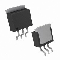
LP2954AISX/NOPB National Semiconductor, LP2954AISX/NOPB Datasheet - Page 8

LP2954AISX/NOPB
Manufacturer Part Number
LP2954AISX/NOPB
Description
IC VREG LDO MCRPWR 5V TO263-3
Manufacturer
National Semiconductor
Datasheet
1.LP2954AIMXNOPB.pdf
(15 pages)
Specifications of LP2954AISX/NOPB
Regulator Topology
Positive Fixed
Voltage - Output
5V
Voltage - Input
6 ~ 30 V
Voltage - Dropout (typical)
0.47V @ 250mA
Number Of Regulators
1
Current - Output
250mA
Operating Temperature
-40°C ~ 125°C
Mounting Type
Surface Mount
Package / Case
TO-263-3, D²Pak (3 leads + Tab), TO-263AA
Lead Free Status / RoHS Status
Lead free / RoHS Compliant
Current - Limit (min)
-
Other names
LP2954AISX
www.national.com
Typical Performance Characteristics
Application Hints
EXTERNAL CAPACITORS
A 2.2 µF (or greater) capacitor is required between the
output pin and the ground to assure stability (refer to Figure
1). Without this capacitor, the part may oscillate. Most types
of tantalum or aluminum electrolytics will work here. Film
types will work, but are more expensive. Many aluminum
electrolytics contain electrolytes which freeze at −30˚C,
which requires the use of solid tantalums below −25˚C. The
important parameters of the capacitor are an ESR of about
5Ω or less and a resonant frequency above 500 kHz (the
ESR may increase by a factor of 20 or 30 as the temperature
is reduced from 25˚C to −30˚C). The value of this capacitor
may be increased without limit. At lower values of output
current, less output capacitance is required for stability. The
capacitor can be reduced to 0.68 µF for currents below
10 mA or 0.22 µF for currents below 1 mA.
A 1 µF capacitor should be placed from the input pin to
ground if there is more than 10 inches of wire between the
input and the AC filter capacitor or if a battery input is used.
Programming the output for voltages below 5V runs the error
amplifier at lower gains requiring more output capacitance
Dropout Characteristics
Current and Maximum
Short-Circuit Output
Output Current
01112826
01112828
8
(Continued)
for stability. At 3.3V output, a minimum of 4.7 µF is required.
For the worst case condition of 1.23V output and 250 mA of
load current, a 6.8 µF (or larger) capacitor should be used.
Stray capacitance to the Feedback terminal can cause insta-
bility. This problem is most likely to appear when using high
value external resistors to set the output voltage. Adding a
100 pF capacitor between the Output and Feedback pins
and increasing the output capacitance to 6.8 µF (or greater)
will cure the problem.
MINIMUM LOAD
When setting the output voltage using an external resistive
divider, a minimum current of 1 µA is recommended through
the resistors to provide a minimum load.
It should be noted that a minimum load current is specified in
several of the electrical characteristic test conditions, so this
value must be used to obtain correlation on these tested
limits. The part is parametrically tested down to 100 µA, but
is functional with no load.
Maximum Power Dissipation
(TO-263) (See (Note 2) )
Thermal Response
01112827
01112811


