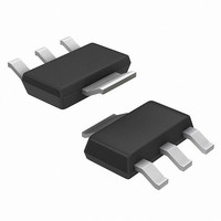
NCP1117ST33T3G ON Semiconductor, NCP1117ST33T3G Datasheet - Page 6

NCP1117ST33T3G
Manufacturer Part Number
NCP1117ST33T3G
Description
IC REG LDO 1A 3.3V SOT223
Manufacturer
ON Semiconductor
Datasheet
1.NCV1117ST50T3G.pdf
(18 pages)
Specifications of NCP1117ST33T3G
Regulator Topology
Positive Fixed
Voltage - Output
3.3V
Voltage - Input
Up to 20V
Voltage - Dropout (typical)
1.07V @ 800mA
Number Of Regulators
1
Current - Limit (min)
1A
Operating Temperature
0°C ~ 125°C
Mounting Type
Surface Mount
Package / Case
SOT-223 (3 leads + Tab), SC-73, TO-261
Number Of Outputs
1
Polarity
Positive
Input Voltage Max
20 V
Output Voltage
3.3 V
Output Type
Fixed
Dropout Voltage (max)
1.1 V at 100 mA
Output Current
1 A
Line Regulation
0.8 mV
Load Regulation
4.3 mV
Voltage Regulation Accuracy
1 %
Maximum Operating Temperature
+ 125 C
Mounting Style
SMD/SMT
Minimum Operating Temperature
0 C
Lead Free Status / RoHS Status
Lead free / RoHS Compliant
Current - Output
-
Lead Free Status / Rohs Status
Lead free / RoHS Compliant
Other names
NCP1117ST33T3GOSTR
Available stocks
Company
Part Number
Manufacturer
Quantity
Price
Company:
Part Number:
NCP1117ST33T3G
Manufacturer:
ON
Quantity:
30 000
Company:
Part Number:
NCP1117ST33T3G
Manufacturer:
ON
Quantity:
168 000
Part Number:
NCP1117ST33T3G
Manufacturer:
ON/安森美
Quantity:
20 000
Company:
Part Number:
NCP1117ST33T3G
Manufacturer:
ON
Quantity:
18 669
100
100
0.1
10
80
60
40
20
0.001
1
0
0
V
V
C
C
T
Region of Instability
A
out
in
out
adj
ESR, EQUIVALENT SERIES RESISTANCE (W)
Figure 10. NCP1117XTA Ripple Rejection
= 25°C
− V
Figure 12. Output Capacitance vs. ESR
= 5.0 V
= 25 mF
= 10 mF
out
200
0.01
= 3.0 V
I
Region of Stability
out
, OUTPUT CURRENT (mA)
vs. Output Current
400
350E−9
300E−9
250E−9
200E−9
150E−9
100E−9
50E−9
0.1
f
V
f
V
0
ripple
ripple
10
ripple
ripple
600
0.1 A
Figure 14. Output Spectral Noise Density vs.
V
V
I
C
T
= 120 Hz
= 20 kHz
load
v 3.0 V
v 0.5 V
in
out
J
in
1 A
= 25°C
= 3.0 V
= 10 mF MLCC
= 1.25 V
= 5 mA − 1 A
1
0.5 A
800
P−P
P−P
100
Frequency, V
http://onsemi.com
FREQUENCY (Hz)
1000
10
1.0 k
6
out
C
C
V
100
0.01
80
60
40
20
in
in
out
0.1
10
0
− V
= 10 mF Tantalum
= 1V5
1
10
= 10 mF Tantalum
0
C
T
out
V
V
I
C
C
out
A
adj
out
in
out
adj
100
= 25°C
10 k
Figure 11. NCP1117XTA Ripple Rejection
= 3.0 V
Figure 13. Typical ESR vs. Output Current
− V
= 0.5 A
= 200 mF, f v 60 Hz
= 5.0 V
= 25 mF, f > 60 Hz
= 10 mF
out
Region of Stability
200
= 3.0 V
f
ripple
100
I
out
300
V
, RIPPLE FREQUENCY (Hz)
, OUTPUT CURRENT (mA)
100 k
ripple
Region of Instability
vs. Frequency
400
v 3.0 V
1.0 k
500
V
P−P
in
− V
600
out
V
V
C
C
T
V
V
J
in
out
in
out
ripple
700
w V
in
= 25°C
= 3.0 V
= 10 mF MLCC
= 1.25 V
− V
= 10 mF
10 k
v 0.5 V
dropout
out
800
w 3.0 V
900 1000
P−P
100 k


