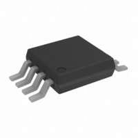
ADP3336ARM-REEL Analog Devices Inc, ADP3336ARM-REEL Datasheet - Page 7

ADP3336ARM-REEL
Manufacturer Part Number
ADP3336ARM-REEL
Description
IC REG LDO ADJ 500MA 8-MSOP TR
Manufacturer
Analog Devices Inc
Series
anyCAP®r
Datasheet
1.ADP3336ARMZ-REEL7.pdf
(9 pages)
Specifications of ADP3336ARM-REEL
Rohs Status
RoHS non-compliant
Design Resources
Analog Audio Input, Class-D Output with ADAU1701, SSM2306, and ADP3336 (CN0162)
Regulator Topology
Positive Adjustable
Voltage - Output
1.5 ~ 10 V
Voltage - Input
2.6 ~ 12 V
Voltage - Dropout (typical)
0.2V @ 500mA
Number Of Regulators
1
Current - Output
500mA
Operating Temperature
-40°C ~ 85°C
Mounting Type
Surface Mount
Package / Case
8-MSOP, Micro8™, 8-uMAX, 8-uSOP,
Current - Limit (min)
-
Output Voltage
The ADP3336 has an adjustable output voltage that can be set
by an external resistor divider. The output voltage will be
divided by R1 and R2, and then fed back to the FB pin.
In order to have the lowest possible sensitivity of the output
voltage to temperature variations, it is important that the paral-
lel resistance of R1 and R2 is always 50 kΩ.
Also, for the best accuracy over temperature the feedback volt-
age should be set for 1.178 V:
where V
bandgap” voltage. Note that V
FB pin due to loading by the internal PTAT current.
Combining the above equations and solving for R1 and R2 gives
the following formulas:
V
1.5 V
1.8 V
2.2 V
2.7 V
3.3 V
5 V
10 V
Paddle-Under-Lead Package
The ADP3336 uses a proprietary paddle-under-lead package
design to ensure the best thermal performance in an MSOP-8
footprint. This new package uses an electrically isolated die
attach that allows all pins to contribute to heat conduction.
This technique reduces the thermal resistance to 110°C/W on a
4-layer board as compared to >160°C/W for a standard MSOP-8
leadframe. Figure 4 shows the standard physical construction
of the MSOP-8 and the paddle-under-lead leadframe.
OUT
A
OUT
is the desired output voltage and V
Table I. Feedback Resistor Selection
R1 (1% Resistor)
63.4 kΩ
76.8 kΩ
93.1 kΩ
115 kΩ
140 kΩ
210 kΩ
422 kΩ
V
FB
R
R
R
R
1 50
=
1
1
2
V
=
×
+
=
OUT
R
R
FB
1
2
2
k
×
50
Ω ×
–
=
does not actually appear at the
V
V
50
k
R
OUT
V
Ω
FB
1
V
R
k
OUT
+
FB
Ω
2
R
2
R2 (1% Resistor)
232 kΩ
147 kΩ
107 kΩ
88.7 kΩ
78.7 kΩ
64.9 kΩ
56.2 kΩ
FB
is the “virtual
Thermal Overload Protection
The ADP3336 is protected against damage from excessive power
dissipation by its thermal overload protection circuit which limits
the die temperature to a maximum of 165°C. Under extreme
conditions (i.e., high ambient temperature and power dissipation)
where die temperature starts to rise above 165°C, the output
current is reduced until the die temperature has dropped to a
safe level. The output current is restored when the die tempera-
ture is reduced.
Current and thermal limit protections are intended to protect
the device against accidental overload conditions. For normal
operation, device power dissipation should be externally limited
so that junction temperatures will not exceed 150°C.
Calculating Junction Temperature
Device power dissipation is calculated as follows:
Where I
and V
Assuming I
V
The proprietary package used in the ADP3336 has a thermal
resistance of 110°C/W, significantly lower than a standard
MSOP-8 package. Assuming a 4-layer board, the junction tem-
perature rise above ambient temperature will be approximately
equal to:
To limit the maximum junction temperature to 150°C, maxi-
mum allowable ambient temperature will be:
Printed Circuit Board Layout Consideration
All surface mount packages rely on the traces of the PC board to
conduct heat away from the package.
OUT
= 3.3 V, device power dissipation is:
OUT
LOAD
P
are input and output voltages respectively.
D
LOAD
= (5 – 3.3) 400 mA + 5.0(4 mA) = 700 mW
and I
P
∆T
D
T
AMAX
= 400 mA, I
= (V
J
A
GND
=
IN
= 150°C – 77.0°C = 73.0°C
0 700
are load current and ground current, V
.
– V
DIE
OUT
W
GND
) I
×
LOAD
110
= 4 mA, V
° =
+ (V
C
77 0
IN
IN
) I
ADP3336
.
= 5.0 V and
GND
°
C
IN


