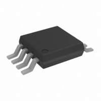
ADP3336ARM-REEL7 Analog Devices Inc, ADP3336ARM-REEL7 Datasheet - Page 8

ADP3336ARM-REEL7
Manufacturer Part Number
ADP3336ARM-REEL7
Description
IC REG LDO ADJ 500MA 8-MSOP
Manufacturer
Analog Devices Inc
Series
anyCAP®r
Datasheet
1.ADP3336ARMZ-REEL7.pdf
(9 pages)
Specifications of ADP3336ARM-REEL7
Design Resources
Analog Audio Input, Class-D Output with ADAU1701, SSM2306, and ADP3336 (CN0162)
Regulator Topology
Positive Adjustable
Voltage - Output
1.5 ~ 10 V
Voltage - Input
2.6 ~ 12 V
Voltage - Dropout (typical)
0.2V @ 500mA
Number Of Regulators
1
Current - Output
500mA
Operating Temperature
-40°C ~ 85°C
Mounting Type
Surface Mount
Package / Case
8-MSOP, Micro8™, 8-uMAX, 8-uSOP,
Lead Free Status / RoHS Status
Contains lead / RoHS non-compliant
Current - Limit (min)
-
Other names
ADP3336ARM-REEL7
ADP3336ARMREEL7TR
ADP3336ARMREEL7TR
ADP3336
In standard packages the dominant component of the heat resis-
tance path is the plastic between the die attach pad and the
individual leads. In typical thermally enhanced packages one or
more of the leads are fused to the die attach pad, significantly
decreasing this component. To make the improvement mean-
ingful, however, a significant copper area on the PCB must be
attached to these fused pins.
The proprietary paddle-under-lead frame design of the ADP3336
uniformly minimizes the value of the dominant portion of the
thermal resistance. It ensures that heat is conducted away by all
pins of the package. This yields a very low 110°C/W thermal
resistance for an MSOP-8 package, without any special board
layout requirements, relying only on the normal traces connected
to the leads. This yields a 33% improvement in heat dissipation
capability as compared to a standard MSOP-8 package. The
thermal resistance can be decreased by, approximately, an addi-
tional 10% by attaching a few square cm of copper area to the
IN pin of the ADP3336 package.
It is not recommended to use solder mask or silkscreen on the
PCB traces adjacent to the ADP3336’s pins since it will increase
the junction-to-ambient thermal resistance of the package.
Shutdown Mode
Applying a TTL high signal to the shutdown (SD) pin or tying
it to the input pin, will turn the output ON. Pulling SD down to
0.4 V or below, or tying it to ground will turn the output OFF.
In shutdown mode, quiescent current is reduced to much less
than 1 µA.
A


