CRCW25120000Z0EG Vishay, CRCW25120000Z0EG Datasheet - Page 6
CRCW25120000Z0EG
Manufacturer Part Number
CRCW25120000Z0EG
Description
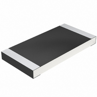
RES 0.0 OHM 1W 2512 SMD
Manufacturer
Vishay
Series
CRCWr
Type
Thick Filmr
Specifications of CRCW25120000Z0EG
Resistance
0 Ohms
Power Rating
1 Watt
Voltage Rating
500 Volts
Operating Temperature Range
- 55 C to + 155 C
Resistance (ohms)
0.0
Power (watts)
1W
Composition
Thick Film
Tolerance
Jumper
Size / Dimension
0.248" L x 0.124" W (6.30mm x 3.15mm)
Height
0.024" (0.60mm)
Lead Style
Surface Mount (SMD - SMT)
Package / Case
2512 (6432 Metric)
Resistance In Ohms
0.0
Case
2512 (6432 metric)
Termination Style
SMD/SMT
Dimensions
3.15 mm W x 6.3 mm L x 0.6 mm H
Product
Thick Film Resistors Zero-Ohm
Resistor Element Material
Thick Film
Resistor Case Style
2512
No. Of Pins
2
Power Rating(s)
Not RequiredW
Tolerance (+ Or -)
Not Required
Temperature Coefficient
Not Required
Operating Temp Range
-55C to 155C
Case Style
Molded
Failure Rate
Not Required
Product Length (mm)
6.3mm
Product Depth (mm)
3.15mm
Product Height (mm)
0.6mm
Construction
Rectangular
Lead Free Status / RoHS Status
Lead free / RoHS Compliant
Features
-
Temperature Coefficient
-
Lead Free Status / Rohs Status
Lead free / RoHS Compliant
Other names
541-0.0XTR
CRCW2512 0R0 E67 E3
CRCW2512 0R0 E67 E3


D/CRCW e3
Vishay
www.vishay.com
130
THE PRODUCT DESCRIBED HEREIN AND THIS DATASHEET ARE SUBJECT TO SPECIFIC DISCLAIMERS, SET FORTH AT
TEST PROCEDURES AND REQUIREMENTS
EN
60115-1
CLAUSE
4.5
4.7
4.13
4.17.2
4.8.4.2
4.32
4.33
4.19
4.23
4.23.2
4.23.3
4.23.4
4.23.5
4.23.6
4.23.7
4.25.1
METHOD
60068-2
21 (Uu
21 (Uu
14 (Na)
30 (Db)
30 (Db)
58 (Td)
13 (M)
2 (Ba)
1 (Aa)
TEST
IEC
-
-
-
-
-
-
-
3
1
)
)
Short time overload
Substrate bending
Climatic sequence:
Rapid change of
Damp heat, cyclic
Damp heat, cyclic
Low air pressure
Voltage proof
Temperature
Solderability
temperature
Resistance
Endurance
(adhesion)
coefficient
DC load
at 70 °C
Dry heat
Shear
TEST
Cold
For technical questions, contact:
Standard Thick Film Chip Resistors
Stability for product types:
RR 1608 and smaller: 9 N
RR 2012 and larger: 45 N
This datasheet is subject to change without notice.
1 kPa; (25 ± 10) °C; 1 h
U =
duration: Acc. to style
Solder bath method;
Solder bath method;
U = 2.5 x
(20/- 55/20) C and
U = 1.4 x U
non activated flux;
non-activated flux;
30 min. at - 55 °C;
55 °C; 90 % RH;
55 °C; 90 % RH;
1.5 h on; 0.5 h off;
30 min. at 125 °C
Sn96.5Ag3Cu0.5
(20/125/20) C
PROCEDURE
U =
24 h; 5 cycles
70 °C; 1000 h
70 °C; 8000 h
Depth 2 mm;
125 °C; 16 h
24 h; 1 cycle
(235 ± 5) °C
(245 ± 5) C
1000 cycles
2 x U
- 55 °C; 2 h
P
Sn60Pb40
(2 ± 0.2) s
(3 ± 0.3) s
5 cycles
70
3 times
P
x R
D/CRCW e3
-
-
70
P
max.
ins
70
x R
U
; 60 s
;
x R
max.
;
thickfilmchip@vishay.com
±0.25 % R + 0.05)
± (0.25 % R + 0.05 )
± (1 % R + 0.05 )
± (1 % R + 0.05 )
± (1 % R + 0.05 )
± (2 % R + 0.1 )
No visible damage, no open circuit in bent position
OR BETTER
± 100 ppm/K
STABILITY
CLASS 1
± 1 %
PERMISSIBLE CHANGE (R)
Good tinning ( 95 % covered)
Good tinning ( 95 % covered)
No flashover or breakdown
± (0.25 % R + 0.05 )
SIZE 0402 to 2512
No visible damage
REQUIREMENTS
no visible damage
no visible damage
1 to 10 M
± (0.5 % R + 0.05 )
±0.5 % R + 0.05)
Document Number: 20035
www.vishay.com/doc?91000
± (1 % R + 0.05 )
± (2 % R + 0.1 )
± (2 % R + 0.1 )
± (4 % R + 0.1 )
OR BETTER
± 200 ppm/K
STABILITY
CLASS 2
Revision: 08-Mar-11
± 5 %
Related parts for CRCW25120000Z0EG
Image
Part Number
Description
Manufacturer
Datasheet
Request
R

Part Number:
Description:
357-036-542-201 CARDEDGE 36POS DL .156 BLK LOPRO
Manufacturer:
Vishay
Datasheet:
Part Number:
Description:
357-036-542-201 CARDEDGE 36POS DL .156 BLK LOPRO
Manufacturer:
Vishay
Datasheet:
Part Number:
Description:
357-036-542-201 CARDEDGE 36POS DL .156 BLK LOPRO
Manufacturer:
Vishay
Datasheet:
Part Number:
Description:
357-036-542-201 CARDEDGE 36POS DL .156 BLK LOPRO
Manufacturer:
Vishay
Datasheet:
Part Number:
Description:
357-036-542-201 CARDEDGE 36POS DL .156 BLK LOPRO
Manufacturer:
Vishay
Datasheet:
Part Number:
Description:
357-036-542-201 CARDEDGE 36POS DL .156 BLK LOPRO
Manufacturer:
Vishay
Datasheet:
Part Number:
Description:
357-036-542-201 CARDEDGE 36POS DL .156 BLK LOPRO
Manufacturer:
Vishay
Datasheet:
Part Number:
Description:
357-036-542-201 CARDEDGE 36POS DL .156 BLK LOPRO
Manufacturer:
Vishay
Datasheet:
Part Number:
Description:
357-036-542-201 CARDEDGE 36POS DL .156 BLK LOPRO
Manufacturer:
Vishay
Datasheet:
Part Number:
Description:
357-036-542-201 CARDEDGE 36POS DL .156 BLK LOPRO
Manufacturer:
Vishay
Datasheet:
Part Number:
Description:
357-036-542-201 CARDEDGE 36POS DL .156 BLK LOPRO
Manufacturer:
Vishay
Datasheet:
Part Number:
Description:
357-036-542-201 CARDEDGE 36POS DL .156 BLK LOPRO
Manufacturer:
Vishay
Datasheet:
Part Number:
Description:
357-036-542-201 CARDEDGE 36POS DL .156 BLK LOPRO
Manufacturer:
Vishay
Datasheet:
Part Number:
Description:
357-036-542-201 CARDEDGE 36POS DL .156 BLK LOPRO
Manufacturer:
Vishay
Datasheet:
Part Number:
Description:
357-036-542-201 CARDEDGE 36POS DL .156 BLK LOPRO
Manufacturer:
Vishay
Datasheet: