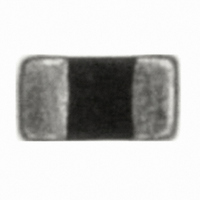
VC060314A300DP AVX Corporation, VC060314A300DP Datasheet - Page 10

VC060314A300DP
Manufacturer Part Number
VC060314A300DP
Description
VARISTOR TVS 14VDC 30A 0603
Manufacturer
AVX Corporation
Series
TransGuard®r
Specifications of VC060314A300DP
Package / Case
0603 (1608 Metric)
Varistor Voltage
18.5V
Current-surge
30A
Number Of Circuits
1
Maximum Ac Volts
10VAC
Maximum Dc Volts
14VDC
Energy
0.10J
Voltage Rating Dc
14 V
Voltage Rating Ac
10 V
Clamping Voltage
32 V
Peak Surge Current
30 Amps
Surge Energy Rating
0.1 J
Capacitance
350 pF
Operating Temperature Range
- 55 C to + 125 C
Current Rating
1 Amp
Dimensions
0.8 mm W x 1.6 mm L x 0.9 mm H
Mounting
SMD/SMT
Product
MLV
Termination Style
SMD/SMT
Brand/series
TransGuard®
Current, Leakage, Maximum
15 μA
Current, Ratings
30 A
Current, Surge
30 A
Energy Rating
0.1 Joules
Mounting Type
SMD
Package Type
0603
Primary Type
Transient Voltage Surge Suppressor
Standards
EIA Approved
Suppressor Type
Multilayer Ceramic Transient Voltage Suppressors
Temperature, Junction, Maximum
125 °C
Temperature, Junction, Minimum
-55 °C
Termination
Solder
Voltage, Breakdown
18.5 V ±12%
Voltage, Clamping
32 V
Voltage, Operating
10/14 VAC/VDC
Voltage, Working
14/10 VDC/VAC
Response Time
Less Than 1 ns
Operation Temp
–55°C to +125°C
Lead Free Status / RoHS Status
Lead free / RoHS Compliant
For Use With
Industrial Equipment
Lead Free Status / RoHS Status
Lead free / RoHS Compliant, Lead free / RoHS Compliant
Other names
478-2499-2
Available stocks
Company
Part Number
Manufacturer
Quantity
Price
Company:
Part Number:
VC060314A300DP
Manufacturer:
AVX
Quantity:
16 000
TransGuard
AVX Multilayer Ceramic Transient Voltage Suppressors
PULSE DEGRADATION
Traditionally varistors have suffered degradation of electrical perfor-
mance with repeated high current pulses resulting in decreased
breakdown voltage and increased leakage current. It has been
suggested that irregular intergranular boundaries and bulk material
result in restricted current paths and other non-Schottky barrier
paralleled conduction paths in the ceramic. Repeated pulsing of
both 5.6 and 14V TransGuard
CAPACITANCE/FREQUENCY
CHARACTERISTICS
TransGuard
10
TYPICAL PERFORMANCE CURVES
100
80
60
40
20
0
0
VC06LC18X500
TransGuard
15%
10%
5%
0%
20
®
10%
8%
6%
4%
2%
0%
Capacitance vs Frequency 0603
Repetitive Peak Current Strikes
Repetitive Peak Current Strikes
0
TransGuard
0
Frequency (MHz)
40
100
100
®
0805 0.1J and 0.3J Products
200
Number of Strikes
60
200
Number of Strikes
®
Figure 2
VC060305A150
1206 0.4J Product
VC060326A580
Figure 1
®
300
transient voltage suppressors with
300
80
VC080518C400
VC080518A400
VC120618D400
VC120626D580
VC120614D300
VC120605D150
®
400
400
100
500
500
TransGuard
100
80
60
40
20
0
0
600
600
20
®
(0603, 0805, 1206 & 1210 CHIP SIZES)
Capacitance vs Frequency 0805
Frequency (MHz)
40
150 Amp peak 8 x 20μS waveforms shows negligible degradation
in breakdown voltage and minimal increases in leakage current.
This does not mean that TransGuard
degradation, but it occurs at much higher current. The plots
of typical breakdown voltage vs number of 150A pulses are
shown below.
60
VC080505C150
VC080518C400
VC080514A300
80
Repetitive Peak Current Strikes
Repetitive Peak Current Strikes
30%
25%
20%
15%
10%
10%
5%
0%
8%
6%
4%
2%
0%
TransGuard
StaticGuard 0805 0.1J Product
100
0
0
100
100
TransGuard
100
80
60
40
20
0
0
®
200
200
Figure 4
Figure 3
Number of Strikes
Number of Strikes
1210 1.5J Product
®
20
Capacitance vs Frequency 1206
300
300
®
VC08LC18A500
suppressors do not suffer
Frequency (MHz)
40
400
400
VC121018J390
500
500
60
VC120614D300
VC120648D101
VC12LC18A500
600
600
80
100


