V275LA20CP Littelfuse Inc, V275LA20CP Datasheet
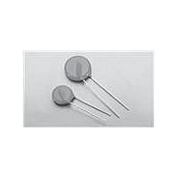
VARISTOR 275V C-III 14MM RADL LA

V275LA20CP

Manufacturer Part Number
V275LA20CP
Description
VARISTOR 275V C-III 14MM RADL LA
Manufacturer
Littelfuse Inc
Series
C-IIIr
Datasheet

Specifications of V275LA20CP

Package / Case
Disc 20mm
Number Of Circuits
1
Energy
145J
Current-surge
5kA
Maximum Ac Volts
275Vrms
Varistor Voltage
389V
Product
MOV
Voltage Rating Dc
275 V
Voltage Rating Ac
275 V
Clamping Voltage
710 V
Peak Surge Current
6 KA
Operating Temperature Range
- 55 C to + 85 C
Mounting
Through Hole
Dimensions
14 mm Dia.
Termination Style
Radial
Lead Free Status / RoHS Status
Lead free / RoHS Compliant
Maximum Dc Volts
-
Lead Free Status / Rohs Status
Lead free / RoHS Compliant
©2009 Littelfuse, Inc.
Specifications are subject to change without notice.
Please refer to www.littelfuse.com/series/c-iii.html for current information.
RoHS
Continuous
Steady State Applied Voltage:
Transients:
Temperature Coefficient (a
Agency Approvals
Absolute Maximum Ratings
CAUTION: Stresses above those listed in "Absolute Maximum Ratings" may cause permanent damage to the device. This is a stress only
rating and operation of the device at these or any other conditions above those indicated in the operational sections of this specification is
not implied.
Agency
C-III Varistor Series
Single-Pulse Peak Current (I
(See Peak Pulse Current Test Waveform)
V
) of Clamping Voltage (V
STG
TM
)
Agency File Number
42201-006
116895E
A
E75961
)
)
TM
C
) at Specified Test Current
) 8/20μs Wave
Varistor Products
Radial Lead Varistors > C-III series
Revision: June 3, 2009
101
Description
The C-III Series of Metal-Oxide Varistors (MOVs) are
specifically designed for applications requiring high surge
energy absorption ratings and superior multiple pulse
absorption rating. This is achieved through a special
dielectric material formulation which also results in
higher repetitive surge ratings than other MOV types.
The C-III Series is primarily intended for use in AC
line Transient Voltage Surge Suppressor (TVSS)
product environment and other similar applications
requiring high transient energy and peak current
capability in a relatively small package size.
Features
compliant option
available. Please see
the device and ratings
specifications table
for more information
absorption capability
W
current capability
I
9000A (8/20μs)
TM
gh energy
TM
3500A to
40J to 530J (2ms)
3500 to 9000
C-III Series
-55 to +125
130 to 660
-55 to +85
40 to 530
5000
1000
<0.0
Units
%/ºC
ºC
ºC
A
V
J
V
Wide operating
voltage range
V
reel for automatic
insertion; Also available
with crimped and/or
trimmed lead styles
85ºC ambient
The C-III Series is
supplied in 10mm,
14mm and 20mm
disc versions with
various lead options
130V to 680V
C-III Varistor Series

Related parts for V275LA20CP

V275LA20CP Summary of contents

Page 1

C-III Varistor Series RoHS Agency Approvals Agency Agency File Number E75961 116895E 42201-006 Absolute Maximum Ratings Continuous Steady State Applied Voltage: ) Transients: Single-Pulse Peak Current (I TM (See Peak Pulse Current Test Waveform STG Temperature ...

Page 2

C-III Series Ratings Lead–free and RoHS Compliant Standard Models Models Part Number Branding Part Number C-III Varistor Series Varistor Products Radial Lead Varistors > C-III series Continuous Maximum V Branding V Energy (2ms)W M(AC) (V) 130 130 130 130 140 ...

Page 3

C-III Series Specifications Lead–free And RoHS Compliant Standard Models Models Diameter (mm) Part Number Part Number 1 Average power dissipation of transients not to exceed 0.6W and 1W for model sizes 14mm and 20mm, respectively. 2 7mm parts also available-contact ...

Page 4

Power Dissipation Ratings Should transients occur in rapid succession, the average power dissipation is the energy (watt-seconds) per pulse times the number of pulses per second. The power so developed must be within the specifications shown on the device. The ...

Page 5

Transient V-I Characteristics Curves (continued) Maximum Clamping Voltage for 14mm Parts V130LA10C(P) – V420LA20C(P) 10,000 MODEL SIZE = 60LA20C(P) V 20LA20C(P) V385LA20C(P) V320LA20C(P) V300LA20C(P) V275LA20C(P) 1,000 V250LA20C(P) V1 0LA10C(P) V130LA10C(P) 100 0.001 0.01 0.1 1 1.0 Figure ...

Page 6

Wave Solder Profile Non Lead–free Profile 300 Maximum Wave 240C 250 200 150 100 0.5 1 1.5 2 2.5 Figure 10 TIME(MINUTES) Physical Specifications Lead Material Soldering Characteristics Method 208E Cured, flame retardant epoxy polymer Insulating Material ...

Page 7

AC Bias Reliability The C-III Series MOVs were designed for use on the AC line. The varistor is connected across the AC line and is biased with a constant amplitude sinusoidal voltage. It should be noted that the definition of ...

Page 8

Product Dimensions (mm) ØD A 25.4 (1.00) Øb CRIMPED AND TRIMMED LEADS CRIMPED AND TRIMMED LEAD e crimp and trimmed leads. This option is supplied to the dimensions shown below *Seating plane interpretation per IEC-60717 V Voltage ...

Page 9

Tape and Reel Specifications SEATING H 1 PLANE ...

Page 10

Part Numbering System BASE PART CODES (See Ratings & Specifications tables and notes below) V XXXX LA For “VARISTOR” V M(AC) (Three or four digits -- 130V to 1,000V) SERIES + PACKAGING / LEAD STYLE DESIGNATOR (See BASE PART CODES ...

Related keywords