DLP-USB232R DLP Design Inc, DLP-USB232R Datasheet
DLP-USB232R
Specifications of DLP-USB232R


Related parts for DLP-USB232R


DLP-USB232R Summary of contents
Page 1
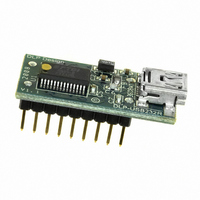
... The internally-generated clock (6MHz, 12MHz, 24MHz and 48MHz) can be brought out of the module and used to drive a microcontroller or external logic. The DLP-USB232R is available in a lead-free (RoHS compliant), compact 18-pin, 0.1-inch standard DIP footprint. FEATURES: • Single chip USB-to-asynchronous serial data-transfer interface. ...
Page 2
... Royalty-Free Virtual COM Port (VCP) Drivers for: • Windows 98, 98SE, ME, 2000, Server 2003, XP and Server 2008 • Windows XP and XP 64-bit • Windows Vista and Vista 64-bit • Windows XP Embedded • Windows CE 4.2, 5.0 and 6.0 Rev. 1.0 (November 2008) 2 © DLP Design, Inc. ...
Page 3
... Windows CE 4.2, 5.0 and 6.0 • Linux 2.4 and greater Note: The drivers listed above are all available for free download from the DLP Design website www.dlpdesign.com and the FTDI website www.ftdichip.com Various third-party drivers are also available for other operating systems; see the FTDI website www ...
Page 4
... FT232R internal EEPROM (see CBUS Signal Options in the next section). 16 RXD - Receiving Asynchronous Data Input DTR - Data Terminal Ready Control Output/Handshake Signal 17 18 TXD - Transmit Asynchronous Data Output Rev. 1.0 (November 2008) Pin 18 Pin 1 USB Pin 10 Pin 9 Top View (Interface Headers on bottom of PCB) 4 © DLP Design, Inc. ...
Page 5
... CBUS SIGNAL OPTIONS The following options can be configured on the CBUS I/O pins in the internal EEPROM using the software utility MPROG, which can be downloaded from www.dlpdesign.com TXDEN# CBUS0, CBUS1, CBUS2, CBUS3, CBUS4 PWREN# CBUS0, CBUS1, CBUS2, CBUS3, CBUS4 TXLED# CBUS0, CBUS1, CBUS2, CBUS3, CBUS4 ...
Page 6
... Select a power source for the DLP-USB232R. The typical configuration for an all 5-volt system is to connect Pins 7, 8 and 9. 3. Connect the DLP-USB232R module to the host PC via a USB-A to Mini-B cable. This action initiates the loading of USB drivers. When prompted, select the folder where the CDM drivers were stored in Step 1 ...
Page 7
... Serial Converter under USB Controllers and select Properties, then the Advanced tab. Check the box marked Load VCP, and then click OK. Unplug and re-plug the DLP-USB232R, and a COM port will be added. [This method is also used to convert from VCP drivers to the D2XX (DLL) drivers.] 2 ...
Page 8
... Figure 3. 3.3V Figure 3 shows how to configure the DLP-USB232R to interface with a 3.3V logic device. In this example, the target electronics provide the 3.3 volts via the VCCIO line (Pin 7) which, in turn, will cause the FT232R interface I/O pins to drive out at the 3.3V level. ...
Page 9
... FT232R EEPROM to inform the system of its power requirements. 4. PWREN# gets its VCC from VCCIO. For designs using 3.3-volt logic, ensure that VCCIO is not powered down during Suspend. Rev. 1.0 (November 2008) P-Channel Power MOSFET .1uF 10K 1K Microcontroller VCC PWREN Power Controlled by PWREN# 9 © DLP Design, Inc. ...
Page 10
... This product and its documentation are supplied on an as-is basis, and no warranty as to their suitability for any particular purpose is either made or implied. DLP Design, Inc. will not accept any claim for damages whatsoever arising as a result of the use or failure of this product. Your statutory rights are not affected ...
Page 11
... This document provides preliminary information that may be subject to change without notice. 5.0 CONTACT INFORMATION DLP Design, Inc. 1605 Roma Lane Allen, TX 75013 Phone: 469-964-8027 Fax: 415-901-4859 Email Sales: sales@dlpdesign.com Email Support: support@dlpdesign.com Website URL: http://www.dlpdesign.com Rev. 1.0 (November 2008) 11 © DLP Design, Inc. ...
Page 12
AGND 7 GND 18 GND 21 GND 26 TEST 4 VCCIO ...