RCWE0402R750FKEA Vishay, RCWE0402R750FKEA Datasheet
RCWE0402R750FKEA
Specifications of RCWE0402R750FKEA


Related parts for RCWE0402R750FKEA

RCWE0402R750FKEA Summary of contents
Page 1
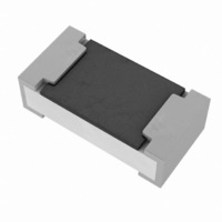
... RCWE Vishay Dale Thick Film Surface Mount Chip Resistors, Wraparound, Extremely Low Value (0.01 Ω to 0.976 Ω) STANDARD ELECTRICAL SPECIFICATIONS POWER RATING GLOBAL P 70 °C MODEL W RCWE0402 0.125 RCWE0603 0.2 RCWE0805 0.25 RCWE1206 0.5 RCWE1210 1.0 RCWE2010 1.0 RCWE2512 2.0 Notes • ...
Page 2
... For technical questions, contact: ff2cresistors@vishay.com Vishay Dale RCWE1206 RCWE1210 RCWE2010 - 155 1 > 300 > 300 > 300 9 > ...
Page 3
... RCWE Thick Film Surface Mount Chip Resistors, Vishay Dale Wraparound, Extremely Low Value (0.01 Ω to 0.976 Ω) Derating PERFORMANCE TEST Thermal shock MIL-STD-202, method 107 ° 125 °C, 300 cycles at each extreme Short time overload High temperature exposure Temperature cycling MIL-STD-202, method 103, 1000 h 85 °C/85 % RH, 10 ...
Page 4
... Vishay product could result in personal injury or death. Customers using or selling Vishay products not expressly indicated for use in such applications their own risk and agree to fully indemnify and hold Vishay and its distributors harmless from and against any and all claims, liabilities, expenses and damages arising or resulting in connection with such use or sale, including attorneys fees, even if such claim alleges that Vishay or its distributor was negligent regarding the design or manufacture of the part ...