HVF1206T5003FE Ohmite, HVF1206T5003FE Datasheet
HVF1206T5003FE
Manufacturer Part Number
HVF1206T5003FE
Description
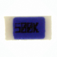
RES 500K OHM 300MW 1% 1206
Manufacturer
Ohmite
Series
HVFr
Datasheet
1.HVF1206T7504FE.pdf
(1 pages)
Specifications of HVF1206T5003FE
Resistance (ohms)
500K
Power (watts)
0.3W
Composition
Thick Film
Temperature Coefficient
±100ppm/°C
Tolerance
±1%
Size / Dimension
0.128" L x 0.063" W (3.25mm x 1.60mm)
Height
0.018" (0.46mm)
Lead Style
Surface Mount (SMD - SMT)
Package / Case
1206 (3216 Metric)
Resistance In Ohms
500K
Case
1206 (3216 metric)
Resistance
500 KOhms
Power Rating
0.3 Watt
Voltage Rating
1.5 KVolts
Termination Style
SMD/SMT
Operating Temperature Range
- 55 C to + 200 C
Dimensions
1.6 mm W x 3.25 mm L x 0.71 mm H
Product
Metal Film Resistors High Reliability
Material, Element
Metal Element
Package Type
1206
Power, Rating
0.3 W
Termination
SMT
Lead Free Status / RoHS Status
Lead free / RoHS Compliant
Features
-
Lead Free Status / Rohs Status
Lead free / RoHS Compliant
Other names
HVF1206T5003FEBK
Ohmite’s High Voltage Flip Chip Series incorporates high accu-
racy screen printing technology to achieve high voltage capability
in a stable flip chip SMD chip resistor package. The HVF Series
offers unmatched performance in comparison to standard chip
resistors. Its unique design provides lower voltage and tempera-
ture coefficients, less noise, tighter tolerances, better stability,
higher resistance values, and higher voltage ratings. HVF is
available in convenient 1206 and 2512 footprints.
F e a t u r e s
• High voltage up to 3,000 volts
• Industry standard sizes
• Working temperature range
• Designed for automatic insertion
D e r a t i n g
Ohmite Mfg. Co.
*Typical values. Voltage coefficient of
Series
1206
2512
1000K
1500K
2000K
2500K
5000K
7500K
100
Ohms
–55°C to 200°C
V o l t a g e c o e f f i c i e n t
resistance strongly depends on the
resistance value. Contact Ohmite for
details.
80
60
40
20
100K
250K
500K
0
10G
25K
50K
75K
High Voltage
Flip Chip
Series
n u m b e r s f o r H V f
0
1G
H V F 1 2 0 6 T 1 0 0 4 J E T
s t a n d a r d p a r t
o f r e s i s t a n c e
10M ..100MΩ
30M ..300MΩ
HVF1206--- HVF2512---
Ambient Temperature, °C
---T2502FE ---T2502FE
---T5002FE ---T5002FE
---T7502FE ---T7502FE
---T1003FE ---T1003FE
---T2503FE ---T2503FE
---T5003FE ---T5003FE
---T1004FE ---T1004FE
---T1504FE ---T1504FE
---T2004FE ---T2004FE
---T2504FE ---T2504FE
---T5004FE ---T5004FE
---T7504FE ---T7504FE
---T1007JE
---T1008JE
100M ..1GΩ
300M ..3GΩ
Resistance
1GΩ .. 5GΩ
3GΩ .. 5GΩ
*Not available for all resistance
values; consult factory
1K ..10MΩ
1K ..30MΩ
50
Range
70°
Case Size
1206
2512
100
1600 Golf Rd., Rolling Meadows, IL 60008 • 1-866-9-OHMITE • Int’l 1-847-258-0300 • Fax 1-847-574-7522 • www.ohmite.com • info@ohmite.com
o r d e r i n g i n f o r m a t i o n
---T1007FE
---T5007FE
TCR
T = 100 ppm
V = 50 ppm*
(-ppm/V)*
<15.00
<29.00
<40.00
<10.00
150
<3.20
<0.80
<4.00
<7.00
VCR
200
Ohms
First 3 digits are
significant; last
digit specifies
number of zeros to
follow. Example:
1006 = 100MΩ
s p e C i F i C a t i o n s
Resistance Range:
Resistance Tolerance: ±1% std.;
Temperature Coefficient:
Coating: Silicone
Solder Pad Material: Silver
Note: HVF Series should not be
used with tin-lead based solder
compositions. Only silver-based
solder compositions are recom-
mended. Care should be taken
in the selection of the solder flux
contained in the solder paste.
Some pastes are "corrosive" and
can damage the coating and
also the resistive layer during the
soldering process at high tem-
perature. PCBs must be properly
cleaned to remove any layers of
moisture containing halides below
the resistor.
(or Halogen Free) solder pastes,
containing for example ROL0 or
similar.
layout to provide a slot, or air
gap, underneath the downward
facing resistor element, thereby
increasing insulation resistance
and reducing the possibility of
capacitive coupling to the PCB.
Under no circumstances should
any copper trace be present in the
layout directly under the resistive
element.
Land pattern dimensions are for
reference only
size
HVF1206
HVF2512
O
1KΩ to 100GΩ
5% for HVF1206 100MΩ-10GΩ
more; 10% for 10GΩ+
±100ppm std.
(PdAg)
Compliant
We recommend Halide Free
It is advisable for the PCB
l a n d p a t t e r n ( i n . )
RoHS
N
Tolerance
0.150 0.040
0.288 0.062
F = 1%
G = 2%
J = 5%
M
Taping Code
blank = bulk package
T = tape & reel
M
L
n
0.080 0.070
0.140 0.164
o
L
Insulation Resistance >10,000 MΩ
Dielectric Strength
Thermal Shock
Overload
Moisture Resistance
Load Life
Per EIA Std. RS-481
Tape
Reel
series
*Use Ohm’s Law (V= √ P*R) to calculate maximum working voltage.
**Maximum available quantity per reel is 3,500 for 1206 size and 2,000 for
2512 size; call 1-866-9-OHMITE for details.
0.069 ±.004
HVF1206 1K-100M 1% std. 300 1,500 0.128 0.063 0.018 0.028
HVF2512 1K-100G 1% std. 1000 3,000 0.252 0.126 0.026 0.032
7.00 ±.079
178.0 ±2.0
1.75 ±0.10
230mm min.–560mm
max. May consist of
carrier and/or cover tape
followed by a minimum
of 160mm of carrier with
sealed cover tape
0.138 ±.002
T
3.5 ±0.05
Ruthenium Oxide
100M-10G
10G-100G 10%
resistance
Trailer
Silicone
range
t a p e a n d r e e l s p e c i f i c a t i o n s
0.059 +.004/-0.0
1.5 +0.10/-0.0
0.157 ±.004
4.0 ±0.10
>1,000 Volt
∆ R/R < 0.1% typ., MIL Std. 202, method 107
0.50% max.
∆ R/R < 0.1% typ., 1,5 x Pnom, 5 sec
0.50% max.
∆ R/R < 0.1% typ., MIL Std. 202,
0.50% max.
∆ R/R < 0.1% typ., 1000 hours at rated power
0.50% max.
tol. (mW) rating* L
5%
p e r f o r m a n c e d a t a
L
DIRECTION OF FEED
Aluminum Oxide
rating Voltage
power
Components
Silver (PdAg)
0.512 ±.008
13.0 ±.20
HVF Series
500 Volt 25 °C 75% relative humidity
25 °C 75% relative humidity
Cond. C (IEC 68 -2 -14)
(do not exceed max. voltage)
method 106 (IEC 68 -2 -3)
(IEC 115 -1)
0.157 ±.004
4.0 ±0.10
0.079 ±.002
2.0 ±0.05
A
Dimensions (in. ±0.008) Qty./
a
W
W
Minimum of 40
empty component
pockets sealed
with cover tape
B
Flip Chip Film
Leader
High Voltage
a t (max.) reel**
0.315 ±.012
0.331 +.059/-0.0
8.4 +1.5/-0.0
0.56 max.
14.2 max.
8.0 ±0.30
1.969 min.
50.0 min.
0.032 ±.004
0.81 ±0.10
1000
1000
std.
3
Related parts for HVF1206T5003FE
Image
Part Number
Description
Manufacturer
Datasheet
Request
R

Part Number:
Description:
RESISTOR POWER 1.0 OHM 50W
Manufacturer:
Ohmite
Datasheet:

Part Number:
Description:
POINTER BAR KNOB, 6.35MM
Manufacturer:
Ohmite
Datasheet:

Part Number:
Description:
HAND WHEEL POINTER KNOB, 9.525MM
Manufacturer:
Ohmite
Datasheet:

Part Number:
Description:
FINGER GRIP KNOB, 3.175MM
Manufacturer:
Ohmite
Datasheet:


Part Number:
Description:
MOUNTING CLIP, 90 SERIES RESISTOR
Manufacturer:
Ohmite
Datasheet:

Part Number:
Description:
ADJUSTABLE LUG FOR DIVIDOHM
Manufacturer:
Ohmite
Datasheet:
Part Number:
Description:
ADJUSTABLE LUG FOR DIVIDOHM
Manufacturer:
Ohmite
Datasheet:


Part Number:
Description:
RESISTOR POWER 1.0 OHM 50W
Manufacturer:
Ohmite
Datasheet:
Part Number:
Description:
HAND WHEEL POINTER KNOB, 9.525MM
Manufacturer:
Ohmite
Datasheet:
Part Number:
Description:
RHEOSTAT REPAIR KIT
Manufacturer:
Ohmite
Datasheet: