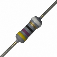
NFR25H0004709JR500 Vishay, NFR25H0004709JR500 Datasheet

NFR25H0004709JR500
Specifications of NFR25H0004709JR500
232220723479
5065FD47R00J12AFX
PPC47BTR
Related parts for NFR25H0004709JR500
NFR25H0004709JR500 Summary of contents
Page 1
... NFR25, NFR25H Vishay BCcomponents Fusible, Non-Flammable Metal Film Leaded Resistors DESCRIPTION A homogeneous film of metal alloy is deposited on a high grade ceramic body. After a helical groove has been cut in the resistive layer, tinned connecting wires of electrolytic copper are welded to the end-caps. The resistors are coated with a grey, flame retardant lacquer which provides electrical, mechanical, and climatic protection ...
Page 2
... TCR/MATERIAL VALUE 0 = Standard 3 digit value 1 digit multiplier MULTIPLIER - * * * * * * TOLERANCE PACKAGING ± filmresistorsleaded@vishay.com NFR25, NFR25H Vishay BCcomponents REEL PIECES CODE 5000 - Ø d Ø d MASS (mm) (mg) 0.58 ± 0.05 201 (1) TOLERANCE PACKAGING SPECIAL J = ± The 2 digits are A5 used for all A1 special parts Standard ...
Page 3
... NFR25, NFR25H Vishay BCcomponents PRODUCTS WITH RADIAL LEADS (NFR25, NFR25H DIMENSIONS (Radial Taping) SYMBOL P Pitch of components Feed-hole centre to lead at topside at the tape 1 P Feed-hole center to body center 2 F Lead-to-lead distance W W Minimum hold down tape width 0 H Component height 1 H Lead wire clinch height ...
Page 4
... P (W) overload ( overload Fusing Characteristics: 15 Ω ≤ filmresistorsleaded@vishay.com NFR25, NFR25H Vishay BCcomponents 100 155 T (°C) amb ) amb ( overload NFR25 This graph is based on measured data which may deviate according to the application. Fusing Characteristics: 1 Ω ≤ ...
Page 5
... NFR25, NFR25H Vishay BCcomponents FUSING CHARACTERISTICS ( NFR25H This graph is based on measured data which may deviate according to the application. Fusing Characteristics: ≤ 1 Ω PULSE LOADING CAPABILITIES ˆ max. ( 1000 NFR25 Pulse on a regular basis; maximum permissible peak pulse power ( ˆ max. ( NFR25 Pulse on a regular basis; maximum permissible peak pulse power ( www ...
Page 6
... For technical questions, contact: Revision: 30-Mar-10 Fusible, Non-Flammable Metal Film Leaded Resistors - 1000 p i 500 200 100 filmresistorsleaded@vishay.com NFR25, NFR25H Vishay BCcomponents - (s) i ˆ function of pulse duration ( max (s) i ˆ function of pulse duration ( max (s) i ˆ function of pulse duration ( max. www.vishay.com ...
Page 7
... NFR25, NFR25H Vishay BCcomponents APPLICATION INFORMATION 100 ΔT ( 0.2 NFR25 Hot-spot temperature rise (Δ function of dissipated power 50 ΔT ( 0.2 Minimum distance from resistor body to P.C. NFR25 Temperature rise (Δ thr lead end (soldering point function of dissipated power at various lead lengths after mounting ...
Page 8
... R ≤ 15 Ω 15 Ω < R ≤ 15 kΩ IEC 60195 Cheese-cloth Maximum voltage max. after 1 min; metal block method filmresistorsleaded@vishay.com NFR25, NFR25H Vishay BCcomponents REQUIREMENTS NFR25 No holes; clean surface; no damage See Dimensions Table - : max. ± nom. Δ max.: ± (0.25 % ...
Page 9
... NFR25, NFR25H Vishay BCcomponents 12NC INFORMATION FOR HISTORICAL CODING REFERENCE • The resistors have a 12 digit numeric code starting with 23 • The subsequent 7 digits indicate the resistor type and packaging • The remaining 3 digits indicate the resistance value: - The first 2 digits indicate the resistance value ...
Page 10
... Vishay product could result in personal injury or death. Customers using or selling Vishay products not expressly indicated for use in such applications their own risk and agree to fully indemnify and hold Vishay and its distributors harmless from and against any and all claims, liabilities, expenses and damages arising or resulting in connection with such use or sale, including attorneys fees, even if such claim alleges that Vishay or its distributor was negligent regarding the design or manufacture of the part ...


