RWM06222201JA15E1 Vishay, RWM06222201JA15E1 Datasheet - Page 2
RWM06222201JA15E1
Manufacturer Part Number
RWM06222201JA15E1
Description
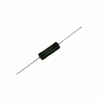
RES WIREWOUND 2.2K OHM 7W
Manufacturer
Vishay
Series
RWMr
Specifications of RWM06222201JA15E1
Resistance
2.2 KOhms
Power Rating
7 Watts
Voltage Rating
350 Volts
Temperature Coefficient
±75ppm/°C
Resistance (ohms)
2.2K
Power (watts)
7W
Composition
Wirewound
Features
Flame Proof
Tolerance
±5%
Size / Dimension
0.256" Dia x 0.709" L (6.50mm x 18.00mm)
Lead Style
Through Hole
Package / Case
Axial
Resistance In Ohms
2.20K
Case
Axial
Termination Style
Axial
Operating Temperature Range
- 55 C to + 200 C
Dimensions
6.5 mm Dia. x 18 mm L
Product
Power Resistors Wire Wound Vitreous Enamel
Dielectric Strength
500 Volts
Resistance Tolerance
± 5%
Resistor Element Material
Thick Film
Lead Free Status / RoHS Status
Lead free / RoHS Compliant
Height
-
Lead Free Status / Rohs Status
Lead free / RoHS Compliant
Other names
RWMB-2.2KTB


OVERLOAD
Heavy overloads can be endured in the form of short pulses
< 0.1 s. Particular requirements should be submitted to
Vishay Sfernice, specifying peak voltage, cycle and
environmental conditions.
RECOMMENDATIONS FOR USE
Since these components are high dissipation power
resistors, customers are advised to use a high melting point
solder.
For low ohmic values, the measurement becomes critical
and the connecting wires resistance is to be included. The
value is measured at 5 mm from the resistor body.
Document Number: 50008
Revision: 16-Oct-09
PERFORMANCE
TESTS
Short Time Overload
Temperature Cycling
Humidity (Steady State)
Terminal Strength
Load Life
ELECTRICAL SPECIFICATIONS
Tolerance
Temperature Coefficient + 75 ppm/°C typical
Dielectric Withstanding Voltage NF EN140000
Inductance
CECC 40201 - EN 140-201
40 °C ambient - R.H. 95 %
Enamelled Wirewound Power Resistors
2 full rotations of 180°
2 successive bending
Tensile test: 20 N
10 P
- 55 °C + 200 °C
CONDITIONS
25 °C ambient
25 °C ambient
For technical questions, contact:
90’/30’ cycle
1000 h at P
r
56 days
during 10 s
Standard
On request
r
Axial Leads
Group Mounting
In a still atmosphere, a distance between axes equal to five
times the resistor’s diameter is recommended.
Cabinet Mounting
•
•
•
These aspects should be considered by the end user.
Unventilated box: Dissipation should be reduced (see
dimensional drawing).
Forced
dissipation may be doubled or even trebled.
In any case: The surface temperature at the hottest point
should not exceed 450 °C.
sfer@vishay.com
REQUIREMENTS
± (1 % + 0.05 Ω)
± (1 % + 0.05 Ω)
± (2 % + 0.1 Ω)
± (5 % + 0.1 Ω)
± (5 % + 0.1 Ω)
Non inductive (Ayrton-Perry) winding available
ventilation:
500 V
± 1 % and ± 2 %
RMS
If
± 5 %
- 1 min - 10 mA
conditions
Vishay Sfernice
TYPICAL DRIFTS
± (0.5 % + 0.05 Ω)
± (0.5 % + 0.05 Ω)
± (0.5 % + 0.05 Ω)
± (0.1 % + 0.05 Ω)
± (1.5 % + 0.05 Ω)
are
www.vishay.com
appropriate,
RWM
89
Related parts for RWM06222201JA15E1
Image
Part Number
Description
Manufacturer
Datasheet
Request
R

Part Number:
Description:
357-036-542-201 CARDEDGE 36POS DL .156 BLK LOPRO
Manufacturer:
Vishay
Datasheet:
Part Number:
Description:
357-036-542-201 CARDEDGE 36POS DL .156 BLK LOPRO
Manufacturer:
Vishay
Datasheet:
Part Number:
Description:
357-036-542-201 CARDEDGE 36POS DL .156 BLK LOPRO
Manufacturer:
Vishay
Datasheet:
Part Number:
Description:
357-036-542-201 CARDEDGE 36POS DL .156 BLK LOPRO
Manufacturer:
Vishay
Datasheet:
Part Number:
Description:
357-036-542-201 CARDEDGE 36POS DL .156 BLK LOPRO
Manufacturer:
Vishay
Datasheet:
Part Number:
Description:
357-036-542-201 CARDEDGE 36POS DL .156 BLK LOPRO
Manufacturer:
Vishay
Datasheet:
Part Number:
Description:
357-036-542-201 CARDEDGE 36POS DL .156 BLK LOPRO
Manufacturer:
Vishay
Datasheet:
Part Number:
Description:
357-036-542-201 CARDEDGE 36POS DL .156 BLK LOPRO
Manufacturer:
Vishay
Datasheet:
Part Number:
Description:
357-036-542-201 CARDEDGE 36POS DL .156 BLK LOPRO
Manufacturer:
Vishay
Datasheet:
Part Number:
Description:
357-036-542-201 CARDEDGE 36POS DL .156 BLK LOPRO
Manufacturer:
Vishay
Datasheet:
Part Number:
Description:
357-036-542-201 CARDEDGE 36POS DL .156 BLK LOPRO
Manufacturer:
Vishay
Datasheet:
Part Number:
Description:
357-036-542-201 CARDEDGE 36POS DL .156 BLK LOPRO
Manufacturer:
Vishay
Datasheet:
Part Number:
Description:
357-036-542-201 CARDEDGE 36POS DL .156 BLK LOPRO
Manufacturer:
Vishay
Datasheet:
Part Number:
Description:
357-036-542-201 CARDEDGE 36POS DL .156 BLK LOPRO
Manufacturer:
Vishay
Datasheet:
Part Number:
Description:
357-036-542-201 CARDEDGE 36POS DL .156 BLK LOPRO
Manufacturer:
Vishay
Datasheet: