B20J1K0E Ohmite, B20J1K0E Datasheet
B20J1K0E
Manufacturer Part Number
B20J1K0E
Description
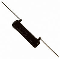
RESISTOR 20W 1000 OHMS 5% AXIAL
Manufacturer
Ohmite
Series
200r
Type
Vitreous Enamel Power Resistorr
Datasheet
1.B8J1R0E.pdf
(1 pages)
Specifications of B20J1K0E
Resistance (ohms)
1K
Power (watts)
20W
Composition
Wirewound
Features
Flame Retardant Coating
Temperature Coefficient
±260ppm/°C
Tolerance
±5%
Size / Dimension
0.437" Dia x 2.000" L (11.11mm x 50.80mm)
Lead Style
Through Hole
Package / Case
Axial
Resistance In Ohms
1.00K
Case
Axial
Resistance
1 KOhms
Power Rating
20 Watts
Termination Style
Axial
Operating Temperature Range
+ 25 C to + 350 C
Dimensions
11.11 mm Dia. x 50.8 mm L
Product
Power Resistors Wire Wound Vitreous Enamel
Voltage Rating
750 Volts
Material, Element
Wirewound
Package Type
Vitreous Enamel
Power, Rating
20 W
Termination
Axial
Voltage, Rating
4 VAC
Lead Free Status / RoHS Status
Lead free / RoHS Compliant
Height
-
Lead Free Status / Rohs Status
Lead free / RoHS Compliant
Available stocks
Company
Part Number
Manufacturer
Quantity
Price

Ohmite’s Brown Devil
small, exceptionally durable
power resistor. It features
all-welded construction and
rugged, flame resistant confor-
mal lead free vitreous enamel
coating to ensure successful
performance under high tem-
peratures.
has a hollow-core construc-
tion, which accommodates
rigid mounting with brackets or
thru bolts.
included with resistors.
F E a t u r E s
• Rugged lead free vitreous enam-
• All-welded construction.
• Self supporting terminal mount-
• Higher power ratings.
• Flame-resistant lead free vitre-
• RoHS compliant product avail-
Ohmite Mfg. Co.
10
11
12
13
15
16
18
0.5 –––R50E
1
1.1 –––1R1E
1.2 –––1R2E
1.3 –––1R3E
1.5 –––1R5E
1.6 –––1R6E
1.8 –––1R8E
2
2.2 –––2R2E
2.4 –––2R4E
2.7 –––2R7E
3
3.3 –––3R3E
3.6 –––3R6E
3.9 –––3R9E
4
4.3 –––4R3E
4.7 –––4R7E
5
5.1 –––5R1E
5.6 –––5R6E
6.2 –––6R2E
6.8 –––6R8E
7.5 –––7R5E
8.2 –––8R2E
9.1 –––9R1E
el coating
ing option.
ous enamel coating.
able. Add “E” suffix to part num-
ber to specify.
The wirewound 200 Series
Mounting brackets not
for mounting hardware
Part No.
Prefix
Suffix
–––1R0E
–––2R0E
–––3R0E
–––4R0E
–––5R0E
–––10RE
–––11RE
–––12RE
–––13RE
–––15RE
–––16RE
–––18RE
See page 36
Wattage
1600 Golf Rd., Rolling Meadows, IL 60008 • 1-866-9-OHMITE • Int’l 1-847-258-0300 • Fax 1-847-574-7522 • www.ohmite.com • info@ohmite.com
®
is a
100 –––100E
110 –––110E
120 –––120E
125 –––125E
130 –––130E
150 –––150E
160 –––160E
180 –––180E
200 –––200E
220 –––220E
225 –––225E
240 –––240E
250 –––250E
20 –––20RE
22 –––22RE
24 –––24RE
25 –––25RE
27 –––27RE
30 –––30RE
33 –––33RE
35 –––35RE
36 –––36RE
39 –––39RE
40 –––40RE
43 –––43RE
47 –––47RE
50 –––50RE
51 –––51RE
56 –––56RE
62 –––62RE
68 –––68RE
75 –––75RE
82 –––82RE
91 –––91RE
Part No.
Prefix
Suffix
s P E C i F i C a t i O N s
Material
Coating: lead free vitreous
Core: Ceramic.
Terminals: Tinned axial; RoHS
Derating: Linearly from
Electrical
Tolerance: 1Ω+: ±5%
Power rating: Based on
Overload: 10 times rated
Temperature coefficient:
To calculate max. amps: use
Coating
Blank = Vitreous
enamel.
solder composition is 96% Sn,
3.5% Ag, 0.5% Cu
100% @ +25°C to 0% @
+350°C.
under 1Ω: ±10%
25°C free air rating.
wattage for 5 seconds.
5Ω and under: ±400 ppm/°C
Above 5Ω: ±260 ppm/°C
the formula √P/R.
C = Centohm
S = Silicone
Wattage
S t a n d a r d p a r t n u m b e r S f o r 2 0 0 S e r i e S
o r d e r i n g i n f o
Series
� �
Wattage
�
1,000 –––1K0E
1,100 –––1K1E
1,200 –––1K2E
1,250 –––1K25E
1,300 –––1K3E
1,500 –––1K5E
1,600 –––1K6E
1,750 –––1K75E
1,800 –––1K8E
2,000 –––2K0E
2,200 –––2K2E
Non-Inductive
Winding
Optional (blank
= std. winding)
270 –––270E
300 –––300E
330 –––330E
350 –––350E
360 –––360E
390 –––390E
400 –––400E
430 –––430E
450 –––450E
470 –––470E
500 –––500E
Tolerance
F = 1%
H = 3%
J = 5%
K = 10%
510 –––510E
560 –––560E
600 –––600E
620 –––620E
650 –––650E
680 –––680E
700 –––700E
750 –––750E
800 –––800E
820 –––820E
900 –––900E
910 –––910E
� � � � �
Part No.
Prefix
Suffix
Ohms
1R0 = 1 Ω
250 = 250 Ω
1K0 = 1,000 Ω
25K = 25,000 Ω
25K5 = 25,500 Ω
Non-Inductive versions available. Insert “N” before tolerance code. Example - B5NJ10RE
Also available in low cost Centohm or Silicone coating. Consult Ohmite.
* Maximum Voltage is based on Ohm’s Law [V=√P*R] as limited by the resistance value of
specified product
series Wattage Ohms
B5
B8
B12
B20
RoHS
Compliant
Wattage
5.25
8.0
12.0
20.0
0.1-20K
0.03-25K 1.000 / 25.40 0.313 / 7.94 0.188 / 4.76
0.08-51K 1.750 / 44.45 0.313 / 7.94 0.188 / 4.76
0.1-100K 2.000 / 50.80 0.438 / 11.11 0.250 / 6.35
See web-
core info
custom
site for
10,000 –––10KE
11,000 –––11KE
12,000 –––12KE
12,500 –––12K5E
13,000 –––13KE
13,500 –––13K5E
15,000 –––15KE
2,250 –––2K25E
2,400 –––2K4E
2,500 –––2K5E
2,700 –––2K7E
2,750 –––2K75E
3,000 –––3K0E
3,300 –––3K3E
3,500 –––3K5E
3,600 –––3K6E
3,900 –––3K9E
4,000 –––4K0E
4,300 –––4K3E
4,500 –––4K5E
4,700 –––4K7E
5,000 –––5K0E
5,100 –––5K1E
5,600 –––5K6E
6,000 –––6K0E
6,200 –––6K2E
6,800 –––6K8E
7,000 –––7K0E
7,500 –––7K5E
8,000 –––8K0E
8,200 –––8K2E
8,500 –––8K5E
9,000 –––9K0E
9,100 –––9K1E
Brown Devil
D
0.625 / 15.88 0.250 / 6.35 0.135 / 3.43
Part No.
Prefix
Suffix
Coating
200 = Vitreous
400 = Silicone
Non-Inductive Winding
Optional (blank
L
= std. winding)
m a d e - t o - o r d e r p a r t S
2 0 0
Ceramic
Dimensions (in. / mm)
Wattage
L
N
®
Vitreous Enamel Power
D
8 D 5 R 0 0 0 J E
Wattage
3
5.25
8
12
20
200 Series
Core Diameter
See “Core and
Terminal Selection”
= Standard values; check
These values involve very fine
resistance wire and should not
be used in critical applications
without burn-in and/or thermal
cycling:
B5: 6.8K-20KΩ
B8: 12.5K-25KΩ
B12: 30K-51KΩ
B20: 22.5K-100KΩ
100,000 –––100KE
16,000 –––16KE
17,500 –––17K5E
18,000 –––18KE
20,000 –––20KE
22,500 –––22K5E
25,000 –––25KE
30,000 –––30KE
35,000 –––35KE
40,000 –––40KE
45,000 –––45KE
50,000 –––50KE
55,000 –––55KE
60,000 –––60KE
65,000 –––65KE
70,000 –––70KE
75,000 –––75KE
80,000 –––80KE
85,000 –––85KE
90,000 –––90KE
95,000 –––95KE
availability using the world-
wide inventory search at
www.ohmite.com
38.10 mm -0/+6.35
Ohms
R500 = 0.500 Ω
1R00 = 1 Ω
250R = 250 Ω
1K00 = 1,000 Ω
25K0 = 25,000 Ω
25K5 = 25,500 Ω
1.50 in. -0/+0.25
C
C
Part No.
Prefix
Suffix
Gauge Volt.*
Lead
20
18
18
18
Tolerance
F = 1%
H = 3%
J = 5%
K = 10%
RoHS
Compliant
Wattage
Max.
187
250
625
750
31
Related parts for B20J1K0E
Image
Part Number
Description
Manufacturer
Datasheet
Request
R

Part Number:
Description:
RESISTOR POWER 1.0 OHM 50W
Manufacturer:
Ohmite
Datasheet:

Part Number:
Description:
POINTER BAR KNOB, 6.35MM
Manufacturer:
Ohmite
Datasheet:

Part Number:
Description:
HAND WHEEL POINTER KNOB, 9.525MM
Manufacturer:
Ohmite
Datasheet:

Part Number:
Description:
FINGER GRIP KNOB, 3.175MM
Manufacturer:
Ohmite
Datasheet:


Part Number:
Description:
MOUNTING CLIP, 90 SERIES RESISTOR
Manufacturer:
Ohmite
Datasheet:

Part Number:
Description:
ADJUSTABLE LUG FOR DIVIDOHM
Manufacturer:
Ohmite
Datasheet:
Part Number:
Description:
ADJUSTABLE LUG FOR DIVIDOHM
Manufacturer:
Ohmite
Datasheet:


Part Number:
Description:
RESISTOR POWER 1.0 OHM 50W
Manufacturer:
Ohmite
Datasheet:
Part Number:
Description:
HAND WHEEL POINTER KNOB, 9.525MM
Manufacturer:
Ohmite
Datasheet:
Part Number:
Description:
RHEOSTAT REPAIR KIT
Manufacturer:
Ohmite
Datasheet: