UPG2179TB-EVAL CEL, UPG2179TB-EVAL Datasheet

EVAL BOARD FOR UPG2179TB

UPG2179TB-EVAL

Manufacturer Part Number
UPG2179TB-EVAL
Description
EVAL BOARD FOR UPG2179TB
Manufacturer
CEL
Type
RFIC Switchr
Datasheet

Specifications of UPG2179TB-EVAL

Contents
Board
Product
RFID Readers
Dimensions
50 mm x 50 mm x 1.6 mm
For Use With/related Products
UPG2179TB
Lead Free Status / RoHS Status
Contains lead / RoHS non-compliant
Document No. PG10454EJ02V0DS (2nd edition)
Date Published March 2004 CP(K)
L, S-band applications. This device operates with dual control voltages of 2.5 to 5.3 V. This device can operate from 0.05 to
3.0 GHz, with low insertion loss and high isolation.
DESCRIPTION
FEATURES
• Switch control voltage
• Low insertion loss
• High isolation
• High-density surface mounting : 6-pin super minimold package (2.0 × 1.25 × 0.9 mm)
APPLICATIONS
• L, S-band digital cellular or cordless telephone
• PCS, W-LAN, WLL and Bluetooth
ORDERING INFORMATION
Caution Observe precautions when handling because these devices are sensitive to electrostatic discharge.
μ
PG2179TB-E4
Remark To order evaluation samples, contact your nearby sales office.
Power
P
a
t r
The
This device is housed in a 6-pin super minimold package, and is suitable for high-density surface mounting.
N
The information in this document is subject to change without notice. Before using this document, please confirm that
this is the latest version.
u
handling
m
μ
b
PG2179TB is a GaAs MMIC L, S-band SPDT (Single Pole Double Throw) switch for mobile phone and other
Part number for sample order:
r e
6-pin super minimold
L, S-BAND MEDIUM POWER SPDT SWITCH
P
a
k c
a
g
e
:
: V
:
: L
:
:
:
: ISL1 = 27 dB TYP. @ f = 0.05 to 2.0 GHz, V
: P
:
S I
V
L
L
L
P
ins1
ins2
ins3
ins4
TM
cont (H)
cont (L)
in (0.1 dB)
in (1 dB)
L
2
etc.
= 0.25 dB TYP. @ f = 0.05 to 1.0 GHz, V
= 0.30 dB TYP. @ f = 1.0 to 2.0 GHz, V
= 0.35 dB TYP. @ f = 2.0 to 2.5 GHz, V
= 0.40 dB TYP. @ f = 2.5 to 3.0 GHz, V
The mark
=
= −0.2 to +0.2 V (0 V TYP.)
2
= 2.5 to 5.3 V (3.0 V TYP.)
= +32.0 dBm TYP. @ f = 0.5 to 3.0 GHz, V
μ
M
4
= +29.0 dBm TYP. @ f = 0.5 to 3.0 GHz, V
PG2179TB-A
G4C
a
d
k r
B
DATA SHEET
n i
T
g
Y
. P
shows major revised points.
• Embossed tape 8 mm wide
• Pin 4, 5, 6 face the perforation side of the tape
• Qty 3 kpcs/reel
@
f
=
2
0 .
o t
3
0 .
G
H
GaAs INTEGRATED CIRCUIT
, z
V
cont (H)
S
cont (H)
cont (H)
cont (H)
cont (H)
u
cont (H)
p
p
μ
y l
= 3.0 V, V
n i
= 3.0 V, V
= 3.0 V, V
= 3.0 V, V
= 3.0 V, V
cont (H)
g
= 3.0 V, V
cont (H)
PG2179TB
NEC Compound Semiconductor Devices 2003, 2004
F
r o
m
= 3.0 V, V
= 3.0 V, V
cont (L)
cont (L)
cont (L)
cont (L)
cont (L)
cont (L)
= 0 V
= 0 V
= 0 V
= 0 V
= 0 V
cont (L)
= 0 V
cont (L)
= 0 V
= 0 V

Related parts for UPG2179TB-EVAL

UPG2179TB-EVAL Summary of contents

Page 1

... L • High isolation : ISL1 = 27 dB TYP 0.05 to 2.0 GHz • Power handling : • High-density surface mounting : 6-pin super minimold package (2.0 × 1.25 × 0.9 mm) APPLICATIONS • L, S-band digital cellular or cordless telephone • PCS, W-LAN, WLL and Bluetooth ORDERING INFORMATION ...

Page 2

PIN CONNECTIONS AND INTERNAL BLOCK DIAGRAM (Top View) (Top View TRUTH TABLE V V INPUT−OUTPUT1 cont1 cont2 Low High High Low ABSOLUTE MAXIMUM RATINGS (T Parameter Symbol Switch Control Voltage V ...

Page 3

ELECTRICAL CHARACTERISTICS (T = +25° 3 cont (H) cont (L) Parameter Symbol ...

Page 4

EVALUATION CIRCUIT 1 000 pF Remark C : 0.05 to 0.5 GHz 1 000 pF O 0.5 to 3.0 GHz 100 pF The application circuits and their parameters are for reference only and are not intended for use in actual ...

Page 5

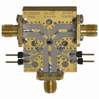
ILLUSTRATION OF THE TEST CIRCUIT ASSEMBLED ON EVALUATION BOARD V cont2 Vc2 INPUT IN Vc1 V cont1 USING THE NEC EVALUATION BOARD Symbol Values C1, C2, C3 100 pF C4 000 pF 6pin SMM SPDT ...

Page 6

TYPICAL CHARACTERISTICS (T = +25° 3 cont (H) cont (L) INPUT–OUTPUT1 INSERTION LOSS vs. FREQUENCY 0.5 0.4 0.3 0.2 0.1 0 –0.1 –0.2 –0.3 –0.4 –0.5 0.5 0.8 1.1 1.4 1.7 2.0 2.3 2.6 2.9 ...

Page 7

INPUT–OUTPUT1 OUTPUT RETURN LOSS vs. FREQUENCY –10 –20 –30 –40 –50 0.5 0.8 1.1 1.4 1.7 2.0 2.3 2.6 2.9 3.2 3.5 Frequency f (GHz) OUTPUT POWER vs. INPUT POWER 1.0 ...

Page 8

PACKAGE DIMENSIONS 6-PIN SUPER MINIMOLD (UNIT: mm) 8 2.1±0.1 1.25±0.1 0.1 MIN. Data Sheet PG10454EJ02V0DS PG2179TB μ ...

Page 9

RECOMMENDED SOLDERING CONDITIONS This product should be soldered and mounted under the following recommended conditions. methods and conditions other than those recommended below, contact your nearby sales office ...

Page 10

Bluetooth is a trademark owned by Bluetooth SIG, Inc., U.S.A. The information in this document is current as of March, 2004. The information is subject to change • without notice. For actual design-in, refer to the latest publications of NEC's ...

Page 11

... Do not lick the product or in any way allow it to enter the mouth. For further information, please contact NEC Compound Semiconductor Devices, Ltd. E-mail: salesinfo@ml.ncsd.necel.com (sales and general) techinfo@ml.ncsd.necel.com (technical) 5th Sales Group, Sales Division TEL: +81-44-435-1588 FAX: +81-44-435-1579 NEC Compound Semiconductor Devices Hong Kong Limited E-mail: ncsd-hk@elhk ...

Related keywords