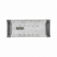
2450AT42B100E Johanson Technology Inc, 2450AT42B100E Datasheet

ANTENNA CHIP 2.4GHZ

2450AT42B100E

Manufacturer Part Number
2450AT42B100E
Description
ANTENNA CHIP 2.4GHZ
Manufacturer
Johanson Technology Inc
Datasheet

Specifications of 2450AT42B100E

Antenna Type
Chip
Number Of Bands
1
Frequency
2.4GHz ~ 2.5GHz
Gain
-1.5dBi
Termination
Surface Mount
Mounting Type
Surface Mount
Height (max)
0.08" (2.1mm)
Lead Free Status / RoHS Status
Lead free by exemption / RoHS Compliant
Vswr
-
Other names
2450AT42B100
712-1008-2
Ground Clearance Requirements Minimized
Detail Specification: 11/20/2008
General Specifications
Part Number
Frequency Range
Peak Gain
Average Gain
Return Loss
Mechanical Dimensions
Mounting Considerations
Mount these devices with brown mark facing up. Units: mm
Line width should be designed to provide 50 Ω impedance matching characteristics.
* Note: Pins 3 & 4, although "No Connect", must be soldered to its PCB pads for proper electrical operation
2450 MHz Antenna
W1
L1
W
L
T
a
JTI P/N for Matching Circuit:
Inductor (1.5nH): L-07C1N5SV6T
Inductor (3.3nH): L-07C3N3SV6T
0.197
0.079
0.102
0.020
0.079
0.020
In
+.004/-.008
±
±
±
±
±
0.008
0.008
0.008
0.008
0.012
"High Frequency Ceramic Solutions"
Johanson Technology, Inc. reserves the right to make design changes without notice.
5.00
2.00
2.60
0.50
2.00
0.50
All sales are subject to Johanson Technology, Inc. terms and conditions.
mm
±
±
±
±
±
+0.1/-0.2
2450AT42B100
2400 - 2500 Mhz
0 dBi typ. (XZ-V)
-1.5 dBi typ. (XZ-V)
9.5 dB min.
0.20
0.20
0.20
0.20
0.30
4001 Calle Tecate • Camarillo, CA 93012 • TEL 805.389.1166 FAX 805.389.1821
L1
L
W1
W
Input Power
Impedance
Operating Temperature
Reel Quanity
2008 Johanson Technology, Inc. All Rights Reserved
www.johansontechnology.com
a
b) With Matching Circuit
a) Without Matching Circuit
T
P/N 2450AT42B100
No.
2
1
2
3
4
3W max.
50 Ω
-40 to +85°C
2,000
* Anchoring Pin-NC
* Anchoring Pin-NC
Anchoring Pin-NC
Feed Point
Function
3
4
Page 1 of 3
1

Related parts for 2450AT42B100E

2450AT42B100E Summary of contents

Page 1

Frequency Ceramic Solutions" 2450 MHz Antenna Ground Clearance Requirements Minimized Detail Specification: 11/20/2008 General Specifications Part Number 2450AT42B100 Frequency Range 2400 - 2500 Mhz Peak Gain 0 dBi typ. (XZ-V) Average Gain -1.5 dBi typ. (XZ-V) Return Loss 9.5 ...

Page 2

Frequency Ceramic Solutions" 2450 MHz Antenna Detail Specification: 11/20/08 Typical Electrical Characteristics (T=25 Test Board Return Loss a) With Matching Circuit Johanson Technology, Inc. reserves the right to make design changes without notice. ...

Page 3

Frequency Ceramic Solutions" 2450 MHz Antenna Detail Specification: 11/20/ Johanson Technology, Inc. reserves the right to make design changes without notice. All sales are subject to Johanson Technology, Inc. terms and conditions. Typical ...

Related keywords