ATAVRRZUSBSTICK Atmel, ATAVRRZUSBSTICK Datasheet
ATAVRRZUSBSTICK
Specifications of ATAVRRZUSBSTICK
Available stocks


Related parts for ATAVRRZUSBSTICK


ATAVRRZUSBSTICK Summary of contents
Page 1
... CE, ETSI and FCC approved. • LCD module (AVRRAVEN): - AT86RF230 radio transceiver with high gain PCB antenna. - Dual AVR microcontrollers. - Dynamic Speaker and microphone. - Atmel Serial Dataflash®. - User IO section: • USART • GPIO • Relay Driver - Powered by battery or external supply: • ...
Page 2
General AVR2016 2 The RZRAVEN kit is built from one RZUSBSTICK module and two AVRRAVEN modules. See Figure 2-1 to Figure 2-4 for further details. The complete schematics and Gerber files are available from the compressed archive accompanying this ...
Page 3
The AVRRAVEN Module 8117D-AVR-04/08 Figure 2-3 Assembly drawing RZUSBSTICK - front view. Figure 2-4 Assembly drawing RZUSBSTICK - back view Figure 3-1 AVRRAVEN overview Joystick Audio LCD 2-way async and user I/O display Serial comm I/O MCU #1: ATmega3290P, ...
Page 4
... AVR Microcontrollers 3.2 Atmel Radio Transceiver 3.3 Antenna description 3.4 LCD AVR2016 4 Two AVR microcontrollers are found on the AVRRAVEN module. An ATmega1284P is connected to the AT86RF230 radio transceiver, and an ATmega3290P is driving the LCD. Both these devices are selected from the AVR picoPower family, something that ensures minimal power consumption and operation down to 1 ...
Page 5
... Volts while the rest of the design will operate down to 1.8Volts A 2-Kbits Atmel Serial EEPROM (AT24C02B) is connected to the ATmega1284P’s two-wire interface (TWI). This storage is write protected by hardware and can only be read. The storage contains important configuration and calibration data that should not be unintentionally overwritten ...
Page 6
Power Supply AVR2016 6 The AVRRAVEN can be powered either from batteries or an external Volts DC source. The power source is selected by the position of the jumper located immediately to the right of the ...
Page 7
Interfaces 8117D-AVR-04/08 The AVRRAVEN module has multiple interfaces that can be used for serial communication, interaction with external sensors and control units such as relays and of course programming and debugging. Figure 3-3 AVRRAVEN User Interfaces Table 3-1. Interfaces ...
Page 8
Programming Interface 3.12.2 Relay Interface 3.13 Voltage Measurement Interface 3.13.1 GPIO AVR2016 8 Both the ATmega3290P and ATmega1284P can be programmed using either the JTAG or ISP interface. JTAG programming can be facilitated by connecting a JTAG ICE mkII ...
Page 9
Table 3-3. ATmega1284P User IO ATmega1284P Port Pin PC0 PC1 PC2 PC3 PC4 PC5 N.C. N.C. PD0 PD1 PD2 PD3 PD4 PD5 PB2 PD7 PA0 PA1 PA2 PA3 PA4 PA5 PA6 PA7 Additional interfaces External power 0V PCB Connection ...
Page 10
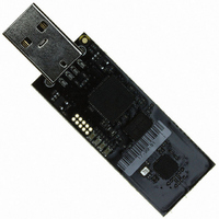
... The AVR RZUSBSTICK Module 4.1 AVR Microcontroller 4.2 Atmel Radio Transceiver 4.3 Antenna description AVR2016 10 Figure 4-1 RZUSBSTICK overview USB interface MCU: AT90USB1287, USB and RF Stacks MCU oscillator 8MHz Xtal The AVR RZUSBSTICK hardware is based a USB microcontroller and a radio transceiver chip. The AT90USB1287 microcontroller handles the USB interface, the AT86RF230 radio transceiver and the RF protocol stacks ...
Page 11
Interfaces 4.4.1 External Memory Interface 4.4.2 Serial Interface 8117D-AVR-04/08 Figure 4-2 RZUSBSTICK Interfaces - front. Figure 4-3 RZUSBSTICK Interfaces - back When necessary the AT90USB1287’s 8k Bytes of internal SRAM can be extended through the AVR external memory interface. ...
Page 12
Programming Interface 4.4.4 LEDs AVR2016 12 A JTAG interface is provided for the AT90USB1287 microcontroller. The interface is available through a 50-mil spaced 10-pin dual row header. The RZRAVEN does not come with the header mounted ...
Page 13
Appendix A: AVRRAVEN Schematics 8117D-AVR-04/08 AVR2016 13 ...
Page 14
AVR2016 14 8117D-AVR-04/08 ...
Page 15
AVR2016 15 ...
Page 16
AVR2016 16 8117D-AVR-04/08 ...
Page 17
AVR2016 17 ...
Page 18
Appendix B: AVRRAVEN Bill of materials AVR2016 18 Table 6-1. AVRRAVEN BOM Qty Designator Description 5 C205, C206, Ceramic capacitor, SMD C207, C220, 0402, NP0, 50V, +/- C221 0.25pF 2 C201, C204 Ceramic capacitor, SMD 0402, NP0, 50V, +/-5% ...
Page 19
... AVR 8-bit RISC MCU AVR2016 Manufacturer Part # 3.3k 10k 47k 100k 470k Murata NCP18WF104J03RB Murata BLM21PG300SN1D Murata BLM21AG102SN1D Johanson L-07C2N7SV6T Technology ST BAT54SWFILM Philips 1PS70SB15 ST SM6T12CA Philips BC847BPN ATMEL AT45DB161D-SU ATMEL AT86RF230-ZU ATMEL AT24C02B-TSU-T Texas Instruments LP2985A-33DBV National LMV934MT Semiconductor ATMEL ATmega1284PV-10MU ATMEL ATmega3290PV-10AU 19 ...
Page 20
Appendix C: AVRRAVEN LCD AVR2016 20 Qty Designator Description 1 U403 TS2007 3W class D audio amp. 2 XC202, XC301 32.768kHz SMD crystal, 85SMX style 1 SP401 PC board speaker, SMD mount 1 XC201 16MHz uXtal GSX-323, 2.0 x ...
Page 21
Table 7-1. LCD Segment description and mapping Registers SEG39 SEG38 SEG37 LCDDR19 SEG31 SEG30 SEG29 LCDDR18 PAN SEG23 SEG22 SEG21 LCDDR17 6C TONE 6M SEG15 SEG14 SEG13 LCDDR16 4C °C ...
Page 22
Appendix D: RZUSBSTICK Schematics AVR2016 22 8117D-AVR-04/08 ...
Page 23
... Kemet C0402C104K4RACTU C0402C105K9PAC 0R 22R 470R 10k Murata BLM21AG102SN1D Philips BC847W TI SN65220YZBR ATMEL AT90USB1287-16MU ATMEL AT86RF230-ZU ATMEL AT24C02B-TSU-T TI LP2985A-33DBV Golledge GSX-323/111BF 16.0MHz Golledge GSX-752B/551EF 8MHz ATMEL A08-0384 SAMTEC USB-AM-S-F-B-SM1-R Everlight EL17-21USRC Everlight EL17-21SYGC Everlight EL17-21UYC/A2 Everlight EL17-21UBC 23 ...
Page 24
... These devices must accept any interference received, including interference that may cause undesired operation. Changes or modifications not expressly approved by Atmel Norway could void the user’s authority to operate the equipment. This equipment has been tested and found to comply with the limits for a Class B digital device, pursuant to Part 15 of the FCC Rules ...
Page 25
... Programming Interface ............................................................................................ 8 3.12.2 Relay Interface ........................................................................................................ 8 3.13 Voltage Measurement Interface ........................................................................ 8 3.13.1 GPIO ....................................................................................................................... 8 4 The AVR RZUSBSTICK Module .................................................... 10 4.1 AVR Microcontroller .......................................................................................... 10 4.2 Atmel Radio Transceiver ................................................................................... 10 4.3 Antenna description........................................................................................... 10 4.4 Interfaces........................................................................................................... 11 4.4.1 External Memory Interface ...................................................................................... 11 4.4.2 Serial Interface ........................................................................................................ 11 4.4.3 Programming Interface ............................................................................................ 12 4.4.4 LEDs........................................................................................................................ 12 5 Appendix A: AVRRAVEN Schematics ...
Page 26
Table of Contents......................................................................... 25 Disclaimer.......................................................................................... 27 AVR2016 26 10.1 FCC Statements.............................................................................................. 24 10.1.1 Equipment usage .................................................................................................. 24 10.1.2 Compliance Statement (Part 15.19) ...................................................................... 24 10.1.3 Warning (Part 15.21) ............................................................................................. 24 10.1.4 Compliance Statement (Part 15.105(b) ) ............................................................... 24 10.1.5 ...
Page 27
... BEEN ADVISED OF THE POSSIBILITY OF SUCH DAMAGES. Atmel makes no representations or warranties with respect to the accuracy or completeness of the contents of this document and reserves the right to make changes to specifications and product descriptions at any time without notice. Atmel does not make any commitment to update the information contained herein. Unless specifically provided otherwise, Atmel products are not suitable for, and shall not be used in, automotive applications. Atmel’ ...