101-1285 Rabbit Semiconductor, 101-1285 Datasheet
101-1285
Specifications of 101-1285


Related parts for 101-1285


101-1285 Summary of contents
Page 1
MiniCore RCM5600W C-Programmable Wi-Fi Core Module OEM User’s Manual 019–0174_F ...
Page 2
MiniCore RCM5600W User’s Manual Part Number 019-0174 • Printed in U.S.A. ©2010 Digi International Inc. • All rights reserved. Digi International reserves the right to make changes and improvements to its products without providing notice. ® ® Rabbit , MiniCore ...
Page 3
Chapter 1: Introduction 1.1 RCM5600W Features ........................................................................................................................... 2 1.2 Advantages of the RCM5600W............................................................................................................ 3 1.3 Development and Evaluation Tools...................................................................................................... 4 1.3.1 RCM5600W Standard Development Kit ....................................................................................4 1.3.2 RCM5600W Deluxe Development Kit .......................................................................................4 1.3.3 Optional Add-Ons .......................................................................................................................5 1.3.4 Software ......................................................................................................................................5 1.3.5 ...
Page 4
Standalone Operation of the RCM5600W ............................................................................... 37 4.5 Other Hardware .................................................................................................................................. 38 4.5.1 Clock Doubler .......................................................................................................................... 38 4.5.2 Spectrum Spreader .................................................................................................................... 38 4.6 Memory .............................................................................................................................................. 39 4.6.1 SRAM ....................................................................................................................................... 39 4.6.2 Flash Memory ........................................................................................................................... 39 4.6.3 Encryption RAM Memory ...
Page 5
... E.3 Using the Serial Communication Accessory Board ......................................................................... 113 E.3.1 Configuration ..........................................................................................................................114 E.3.2 Add Additional Boards ...........................................................................................................116 Appendix F: Power Supply F.1 Power Supplies ................................................................................................................................. 117 F.1.1 Battery Backup ........................................................................................................................118 F.1.2 Battery-Backup Circuit ...........................................................................................................119 F.1.3 Reset Generator .......................................................................................................................119 F.1.4 Onboard Power Supplies .........................................................................................................120 93 101 109 117 ...
Page 6
...
Page 7
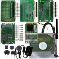
The RCM5600W MiniCore module provides a compact module in a mini PCI Express form factor with integrated Wi-Fi/802.11b/g functionality to allow you to create a low-cost, low-power, Wi-Fi based control and communications solution for your embedded system. A Development Kit ...
Page 8
RCM5600W Features • Small size: 1.20" × 2.00" × 0.40" (30 mm × × 10 mm) • Microprocessor: Rabbit 5000 running at 73.73 MHz • general-purpose I/O lines each configurable with up to four ...
Page 9
Advantages of the RCM5600W • Fast time to market using a fully engineered, “ready-to-run/ready-to-program” micro- processor core. • Competitive pricing when compared with the alternative of purchasing and assembling individual components. • Easy C-language program development and debugging • ...
Page 10
Development and Evaluation Tools 1.3.1 RCM5600W Standard Development Kit The RCM5600W Standard Development Kit contains the hardware essentials you will need to use your RCM5600W module. These items are supplied in the standard version of the Development Kit. • ...
Page 11
... The universal AC adapter is available for customers who purchased the Standard Development Kit. This universal AC adapter may be used if your RCM5600W does not work when you power it through the USB cable, and you do not have your own + power supply. • Antenna Add-On Kit (Part No. 101-1295) 2.4 GHz dipole antenna ...
Page 12
Certifications The systems integrator and the end-user are ultimately responsible for the channel range and power limits complying with the regulatory requirements of the country where the end device will be used. Dynamic C function calls and sample programs ...
Page 13
Labeling Requirements (FCC 15.19) FCC ID: MCQ-MCWIFI This device complies with Part 15 of FCC rules. Operation is subject to the following two conditions: (1) this device may not cause harmful interference, and (2) this device must accept any interference ...
Page 14
Industry Canada Labeling RCW5600W This Class B digital apparatus complies with Canadian standard ICES-003. Cet appareil numérique de la classe B est conforme à la norme NMB-003 du Canada. RCW5650W This Class B digital apparatus complies with Canadian standard ...
Page 15
Europe The marking shall include as a minimum: • the name of the manufacturer or his trademark; • the type designation; • equipment classification, (see below). Receiver Class Highly reliable SRD communication media, e.g., serving human life 1 inherent ...
Page 16
MiniCore RCM5600W ...
Page 17
This chapter describes the RCM5600W hardware in more detail, and explains how to set up and use the accompanying Interface Board. NOTE: This chapter (and this manual) assume that you have the RCM5600W Develop- ment Kit. If you purchased an ...
Page 18
Hardware Connections There are four4 steps to connecting the Interface Board for use with Dynamic C and the sample programs: 1. Insert standoffs/connectors on the Interface Board. 2. Install the RCM5600W module on the Interface Board. 3. Connect antenna. ...
Page 19
Step 2 — Install Module on Interface Board Position the RCM5600W module with the edge connectors facing the mini PCI Express socket J1A at an angle as shown in Figure 3 below. Insert the edge connectors into the mini ...
Page 20
Step 3 — Connect Antenna Install the antenna U.FL to RP-SMA connector cable in the bracket using two lockwashers and the nut as shown in the insert in Figure 4. Connect the wire to connector P1 on the RCM5600W, ...
Page 21
Your PC should recognize the new USB hardware, and the LEDs next to the USB connec- tor on the Interface Board will flash — if you get an error message, you will have to install USB drivers. Drivers for Windows ...
Page 22
First, prepare the AC adapter for the country where it will be used by selecting the plug. The deluxe Development Kit presently includes Canada/Japan/U.S., Australia/N.Z., U.K., and European style plugs. Snap in the top of the plug assembly into the ...
Page 23
Troubleshooting It may be possible that your PC or laptop is unable to deliver enough current through the USB connection if you are not using a separate power supply. The RCM5600W will not operate in this case, and the ...
Page 24
Where From Here? If the sample program ran fine, you are now ready other sample programs and to develop your own applications. The source code for the sample programs is provided to ...
Page 25
R To develop and debug programs for the RCM5600W (and for all other Rabbit hardware), you must install and use Dynamic C. This chapter provides a tour of its major features with respect to the RCM5600W. 3.1 Introduction To ...
Page 26
Sample Programs Of the many sample programs included with Dynamic C, several are specific to the RCM5600W. These programs will be found in the programs in the folder one level up are generic samples that can be run on ...
Page 27
The Digital I/O accessory board may also be used to run the sample programs. This accessory board is included only with the SERIALTOSERIAL.C Deluxe Development Kit. To install the Digital I/O accessory board, insert the strip of header pins included ...
Page 28
The sample program is in the SERIALTOSERIAL.C folder. —monitors switches S1, S2, S3, and S4 on the Digital I/O acces- • SERIALTOSERIAL.C sory board and lights LEDs DS1–DS4 when the corresponding pushbutton switch is pressed. LEDs DS1–DS2 on the Digital ...
Page 29
Chapter 4 describes the hardware components and principal hardware subsystems of the RCM5600W. Appendix A, “RCM5600W Specifica- tions,” provides complete physical and electrical specifications. Figure 7 shows the Rabbit-based subsystems designed into the RCM5600W. Figure 7. RCM5600W Subsystems OEM User’s ...
Page 30
RCM5600W Digital Inputs and Outputs Figure 8 shows the RCM5600W pinouts for the edge connector. The edge connectors are designed to interface with a 52-pin mini PCI Express socket. 24 Figure 8. RCM5600W Pinouts MiniCore RCM5600W ...
Page 31
Figure 9 shows the use of the Rabbit 5000 microprocessor ports in the RCM5600W mod- ules. Figure 9. Use of Rabbit 5000 Ports The ports on the Rabbit 5000 microprocessor used in the RCM5600W are configurable, and so the factory ...
Page 32
Table 2. RCM5600W Pinout Configurations Pin Pin Name Default Use 1 GND 2 +3 3–6 n.c. 7 LNK 8 ACT 9 PE0 Input/Output 10 PE1 Input/Output 11 PE2 Input/Output 12 PE3 Input/Output 13 PE5 Input/Output 26 Alternate Use ...
Page 33
Table 2. RCM5600W Pinout Configurations (continued) Pin Pin Name 14 PE6 Input/Output 15 PE7 Input/Output 16 /RESET_IN Input 17 PD0 Input/Output 18 PD1 Input/Output 19 PD2 Input/Output 20 PD3 Input/Output OEM User’s Manual Default Use Alternate Use I/O Strobe I6 ...
Page 34
Table 2. RCM5600W Pinout Configurations (continued) Pin Pin Name Default Use 21 PC0 Input/Output 22 PC1 Input/Output 23 PC2 Input/Output 24 PC3 Input/Output 25 PC4 Input/Output 26 PC5 Input/Output 27 PB0 Input/Output 28 /RESET Reset output 29 PB2 Input/Output 30 ...
Page 35
Table 2. RCM5600W Pinout Configurations (continued) Pin Pin Name 33 PB6 Input/Output 34 PB7 Input/Output 35–42 PA[0:7] Input/Output 43 /IORD Output 44 VBAT_EXT Battery input 45 /IOWR Output 46 PB1 Input/Output 47 STATUS Output 48 PC6 Input/Output 49 SMODE Input ...
Page 36
Memory I/O Interface The Rabbit 5000 address lines (A0–A19) and data lines (D0–D7) are routed internally to the onboard SRAM. I/0 write (/IOWR) and I/0 read (/IORD) are available for interfacing to external devices. Parallel Port A can also ...
Page 37
Serial Communication The RCM5600W board does not have any serial level converters directly on the board. However, an Ethernet or other serial interface may be incorporated on the board the RCM5600W is mounted on. For example, the Serial Communication ...
Page 38
Table 3 summarizes the possible parallel port pins for the serial ports and their clocks. Table 3. Rabbit 5000 Serial Port and Clock Pins TXA PC6, PC7 Serial Port A RXA PC7,PE7 SCLKA PB1 TXB PC4, PC5 Serial Port B ...
Page 39
Wi-Fi Figure 10 shows a functional block diagram for the Wi-Fi circuits. Figure 10. RCM5600W Wi-Fi Block Diagram The Wi-Fi transmission is controlled by the Rabbit 5000 chip, which contains the Wi-Fi Media Access Control (MAC). The Rabbit 5000 ...
Page 40
Table 4. Wi-Fi Channel Allocations Center Frequency Channel (not used) * These channels are disabled for units delivered for sale in the United States ...
Page 41
The following regions have macros and region numbers defined for convenience. Table 5. Worldwide Wi-Fi Macros and Region Numbers Region Americas IFPARAM_WIFI_REGION_AMERICAS IFPARAM_WIFI_REGION__MEXICO_INDO ORS Mexico IFPARAM_WIFI_REGION_MEXICO_OUTDO ORS Canada IFPARAM_WIFI_REGION_CANADA Europe, Middle East, IFPARAM_WIFI_REGION_EMEA Africa, except France France IFPARAM_WIFI_REGION_FRANCE Israel IFPARAM_WIFI_REGION_ISRAEL ...
Page 42
Programming Modes The USB cable is used to connect the programming port of the RCM5600W USB port via the Interface Board. Whenever the RCM5600W is reset, the operating mode is determined by the state of the ...
Page 43
Standalone Operation of the RCM5600W The RCM5600W must be programmed via the Interface Board or via a similar arrange- ment on a customer-supplied board. Once the RCM5600W has been programmed success- fully, reset the RCM5600W. The RCM5600W may be ...
Page 44
Other Hardware 4.5.1 Clock Doubler The RCM5600W takes advantage of the Rabbit 5000 microprocessor’s internal clock dou- bler. A built-in clock doubler allows half-frequency crystals to be used to reduce radiated emissions. The 73.73 MHz frequency specified for the ...
Page 45
Memory 4.6.1 SRAM RCM5600W boards have 1MB of SRAM installed at U10. 4.6.2 Flash Memory RCM5600W boards have 1MB of serial flash memory installed at U4. The RCM5650W has 4MB of serial flash memory installed at U4. A “user ...
Page 46
MiniCore RCM5600W ...
Page 47
Dynamic integrated development system for writing embedded software. It runs on a Windows-based PC and is designed for use with single-board computers and other devices based on the Rabbit microprocessor. Chapter 5 describes the libraries and function ...
Page 48
Dynamic C has a number of standard features. • Full-feature source and/or assembly-level debugger, no in-circuit emulator required. • Royalty-free TCP/IP stack with source code and most common protocols. • Hundreds of functions in source-code libraries and sample programs: ...
Page 49
... For more information, see the Dynamic C Function Reference Manual and Rabbit Semiconductor’s Technical Note TN213, Rabbit Serial Port Software, both included with the online documentation. ...
Page 50
Serial Flash Memory Use The RCM5600W module has a serial flash memory that contains the user block and stores the application program. Two function calls are provided to work with the serial boot flash. These function calls are in ...
Page 51
Src, unsigned len); DESCRIPTION Writes len bytes (up to 64K) to physical address flashDst from Src. Keep calling sbfWriteFlash() until it returns zero or a negative error code. A pos- itive return value indicates that ...
Page 52
User and ID Blocks The sample program USERBLOCK_INFO.C folder can be used to determine the version of the ID block, the size of the ID and user blocks, whether or not the ID/user blocks are mirrored, the total amount ...
Page 53
Interface 5.2.6 Board Function Calls The function calls described in this section are for use with the Interface Board features. The source code is in the Dynamic C library if you need to modify it for your own board design. ...
Page 54
Upgrading Dynamic C Dynamic C patches that focus on bug fixes are available from time to time. Check the Web site www.rabbit.com/support/ 5.3.1 Add-On Modules Starting with Dynamic C version 10.40, Dynamic C includes the popular µC/OS-II real- time ...
Page 55
U 6.1 Introduction to Wi-Fi Wi-Fi, a popular name for 802.11b/g, refers to the underlying technology for wireless local area networks (WLAN) based on the IEEE 802.11 suite of specifications conforming to standards defined by IEEE. IEEE 802.11b describes ...
Page 56
Commands issued to the chip set in the interface allow a host program to override the default configurations and execute functions implemented on the interface cards, for example, scanning for hosts ...
Page 57
Running Wi-Fi Sample Programs In order to run the sample programs discussed in this chapter and elsewhere in this manual, 1. Your module must be plugged in to the Interface Board as described in Chapter 2, “Get- ting Started.” ...
Page 58
Wi-Fi Setup Figure 12 shows how your development setup might look once you’re ready to proceed. 52 Figure 12. Wi-Fi Host Setup MiniCore RCM5600W ...
Page 59
What Else You Will Need Besides what is supplied with the RCM5600W Development Kits, you will need a PC with an available USB port to program the RCM5600W module. You will need either an access point for an existing ...
Page 60
Configuration Information 6.2.3.1 Network/Wi-Fi Configuration Any device placed on an Ethernet-based Internet Protocol (IP) network must have its own IP address. IP addresses are 32-bit numbers that uniquely identify a device. Besides the IP address, we also need a ...
Page 61
PC/Laptop/PDA Configuration This section shows how to configure your PC or notebook to run the sample programs. Here we’re mainly interested in the PC or notebook that will be communicating wirelessly, which is not necessarily the PC that is ...
Page 62
... IP Address select TCP/IP Specify an IP Address and click on “Properties” to fill in the fol- lowing fields: IP Address : 10.10.6.101 Netmask : 255.255.255.0 Default gateway : 10.10.6.1 TIP: If you are using a PC that is already on a network, you will disconnect the PC from that network to run these sample programs ...
Page 63
Once the PC or notebook is set up, we're ready to communicate. You can use Telnet or a Web browser such as Internet Explorer, which come with most Windows installations, to use the network interface, and you can use HyperTerminal ...
Page 64
Any attempt to operate a device outside the allowed channel range or power limits will void your regulatory approval to operate the device in that country. Before you compile and run this sample program, uncomment ...
Page 65
Before you compile and run this sample program, check the TCP/IP configuration parameters, the IP address, and the SSID in the macros, which are reproduced below. #define TCPCONFIG 1 // #define WIFI_REGION_VERBOSE #define PING_WHO "10.10.6.1" #define _PRIMARY_STATIC_IP "10.10.6.170" #define IFC_WIFI_SSID ...
Page 66
You do not need to configure the SSID of your network since that is done from the access point names. Now configure the access to the two access points. // First Access Point #define AP_0 "test1" #define AP_0_LEN strlen(AP_0) #define ...
Page 67
RCM5600W and scans for other Wi-Fi devices that are • WIFISCAN.C operating in either the ad-hoc mode or through access points in the infrastructure mode. No network parameter settings are needed since the RCM5600W does not actually join ...
Page 68
... Authentication should be set to “open system,” which basically means that knowing the key is sufficient to allow access. #define IFC_WIFI_WPA_PSK_HEXSTR \ "1010101010101010101010101010101010101010101010101010101010101010" TIP: There is a good chance of typos since the key is long. First, enter the key in this sample program macro, then copy and paste it to your access point. This ensures that both the RCM5600W and the access point have the same key ...
Page 69
Once you have compiled the sample program and it is running, LED DS1 will go on with a brief toggle off when a ping is sent. LED DS1 will go off for a longer duration when a ping is received. ...
Page 70
PINGLED_STATS.C receiver/transmitter statistics in the Dynamic C Before you compile and run this sample program, change to the host and SSID you want to ping. You may modify SSID the amount of time in ...
Page 71
The Digital I/O accessory board may also be used to run the and sample programs. This accessory board is included only with the PINGLED_STATS.C Deluxe Development Kit. To install the Digital I/O accessory board, insert the strip of header pins ...
Page 72
Web page. • BROWSELED.C Four “device LEDs” are created along with four buttons to toggle them. Users can use their Web browser to change the status of the lights. The DS1, DS2, ...
Page 73
The Serial Communication accessory board needs to be installed to run the sample program. This accessory board is included only with the Deluxe Develop- WIFI.C ment Kit. To install the Serial Communication accessory board, insert the strip of header pins ...
Page 74
Each serial port can be associated with a specific TCP port. The Rabbit will listen on each of these TCP ports for a connection, which will then be associated with a specific serial port. Data will then be shuttled between ...
Page 75
Dynamic C Wi-Fi Configurations Rabbit has implemented a packet driver for the RCM5600W that functions much like an Ethernet driver for the Dynamic C implementation of the TCP/IP protocol stack. In addi- tion to functioning like an Ethernet packet ...
Page 76
Your Own Channel— IFC_WIFI_CHANNEL The default is shown below. #define IFC_WIFI_CHANNEL 0 The default means that any valid channel may be used by the requested SSID. This 0 parameter is mandatory when creating an ad-hoc network. While it is ...
Page 77
These macros specify the WEP keys to use for WEP encryption. These keys can be either 40-bit or 104-bit (i.e., 5 bytes or 13 bytes). They must be defined as a comma- separated list of byte values. Note that you ...
Page 78
The following authentication options are available. IFPARAM_WIFI_AUTH_OPEN — • IFPARAM_WIFI_AUTH_SHAREDKEY — • for WEP only) . IFPARAM_WIFI_WPA_PSK — • TKIP and CCMP only) • Fragmentation threshold— threshold. Frames (or packets) that are larger than this threshold are split into multiple ...
Page 79
Configuring TCP/IP at Run Time There is one basic function call used to configure Wi-Fi and other network settings — . See the Dynamic C TCP/IP User’s Manual, Volume 1 for more informa- ifconfig() tion about this function call. ...
Page 80
Where From Here? NOTE: If you purchased your RCM5600W through a distributor or through a Rabbit part- ner, contact the distributor or partner first for technical support. If there are any problems at this point: • ...
Page 81
Appendix A provides the specifications for the RCM5600W. OEM User’s Manual A A. RCM5600W PPENDIX S PECIFICATIONS 75 ...
Page 82
A.1 Electrical and Mechanical Characteristics Figure A-1 shows the mechanical dimensions for the RCM5600W and RCM5650W. Figure A-1. RCM5600W and RCM5650W Dimensions 76 MiniCore RCM5600W ...
Page 83
It is recommended that you allow for an “exclusion zone” of 0.08" (2 mm) around the RCM5600W top and bottom and 0.04" (1 mm) around the three non-connector edges when the RCM5600W is incorporated into an assembly that includes other ...
Page 84
Table A-1 lists the electrical, mechanical, and environmental specifications for the RCM5600W and RCM5650W. Table A-1. RCM5600W and RCM5650W Specifications Parameter Microprocessor EMI Reduction Serial Flash Memory (program) SRAM Backup Battery parallel digital I/0 lines configurable with ...
Page 85
Table A-1. RCM5600W and RCM5650W Specifications (continued) Parameter Power Operating Temperature Humidity Connectors Board Size Typical Average Antenna Output Power Compliance OEM User’s Manual RCM5600W 3. (min.) – 3. (max.) 625 mA @ 3.3 V while ...
Page 86
A.1.1 mini PCI Express Connector Design Recommendations The RCM5600W is mounted on the Interface Board via a mini PCI Express connector and a corresponding locking latch connector. These are offered by manufacturers as a matched set, although in some cases ...
Page 87
Other manufacturers such as Molex offer similar connectors and latches, but these can have different mechanical structures and PCB footprints to what we use on the Interface Board. Table A-3 lists a pair of matched Molex parts that might be ...
Page 88
... PCI Express Connector Height 6.8 mm 9.2 mm The Rabbit store sells an accessory kit (Part No. 101-1306) with the standoffs, screws, and mini PCI Express connector needed to mount an RCM5600W using the footprint shown in Figure A-4. The heights of the mini PCI Express connec- tor and the associated standoffs in the accessory kit are shown in millimeters at right ...
Page 89
A PPENDIX Appendix B describes the features and accessories of the Inter- face Board, and explains the use of the Interface Board to dem- onstrate the RCM5600W. The Interface Board has power-supply connections and a USB interface to program the ...
Page 90
B.1 Introduction The Interface Board included in the Development Kit makes it easy to connect an RCM5600W module to a power supply and a PC workstation for development. The Interface Board is shown below in Figure B-1, with its main ...
Page 91
B.1.1 Interface Board Features —Power is supplied to the Interface Board either from the PC via • Power Connection the USB connection or through a power supply jack, J6. A chip at U4 disconnects the USB power supply from the ...
Page 92
B.2 Mechanical Dimensions and Layout Figure B-2 shows the mechanical dimensions and layout for the Interface Board. Figure B-2. Interface Board Dimensions Table B-1 lists the electrical, mechanical, and environmental specifications for the Inter- face Board. Table B-1. Interface Board ...
Page 93
B.2.1 Headers The Interface Board has a header socket at J2 for physical connection to other boards × 25 SMT header socket with a 0.1" pin spacing. Figure B-3 shows the layout of another board to ...
Page 94
B.3 Power Supply The RCM5600W requires a regulated 3.15 V – 3. power source to operate. Depending on the amount of current required by the application, different regulators can be used to supply this voltage. The Interface Board ...
Page 95
B.4 Using the Interface Board The Interface Board is also a demonstration board. It can be used to demonstrate the func- tionality of the RCM5600W right out of the box without any modifications to either board. The Interface Board comes ...
Page 96
B.4.1 Add Additional Boards The Prototyping Board and the two accessory boards included with the Deluxe Develop- ment Kit may be installed on the Interface Board as shown in Figure B-6. Figure B-6. Install Additional Boards on Interface Board 1. ...
Page 97
B.5 Interface Board Jumper Configurations Figure B-7 shows the header locations used to configure the various Interface Board options via jumpers. Figure B-7. Location of Configurable Jumpers on Interface Board Table B-2 lists the configuration options using either jumpers or ...
Page 98
MiniCore RCM5600W ...
Page 99
A PPENDIX Appendix C describes the features and accessories of the Proto- typing Board, and explains the use of the Prototyping Board to build prototypes of your own circuits. The Prototyping Board mounts on the Interface Board from which it ...
Page 100
C.1 Introduction The Prototyping Board included in the Development Kit provides a prototyping area for more advanced hardware development. The Prototyping Board is shown below in Figure C-1, with its main features identified. C.1.1 Prototyping Board Features Power Connection —Power ...
Page 101
C.2 Mechanical Dimensions and Layout Figure C-2 shows the mechanical dimensions and layout for the Prototyping Board. Figure C-2. Prototyping Board Dimensions OEM User’s Manual 95 ...
Page 102
Table C-1 lists the electrical, mechanical, and environmental specifications for the Proto- typing Board. Table C-1. Prototyping Board Specifications Parameter Board Size Operating Temperature Humidity Operating Voltage Current Draw from Interface Board (excluding user-added circuits) Prototyping Area Connectors Standoffs/Spacers 96 ...
Page 103
C.2.1 Headers The Prototyping Board has a header socket at J2 for physical connection to other boards above it, and a header socket at J12 on the bottom side to connect to boards below it. J2 and J12 are 2 ...
Page 104
C.3 Using the Prototyping Board The Prototyping Board provides the user with RCM5600W connection points brought out conveniently to labeled points below header J2. The pinouts for header socket J2 are shown in Figure C-4. Figure C-4. MiniCore Boards Pinout ...
Page 105
C.3.1 Add Additional Boards The Prototyping Board and the two accessory boards included with the Deluxe Develop- ment Kit may be installed on the Interface Board as shown in Figure C-5. Figure C-5. Install Additional Boards 1. Insert the header ...
Page 106
MiniCore RCM5600W ...
Page 107
... I/O accessory board, and explains how to use the Digital I/O accessory board. The Digital I/O accessory board mounts on the Interface Board or other board already installed on the Interface Board from which it receives its power and signals. OEM User’s Manual D. D I/O A IGITAL CCESSORY B OARD 101 ...
Page 108
D.1 Introduction The Digital I/O accessory board included in the Deluxe Development Kit provides Push- button switches and LEDs to use in conjunction with selected sample programs. The Dig- ital I/O accessory board is shown below in Figure D-1, with ...
Page 109
D.2 Mechanical Dimensions and Layout Figure D-2 shows the mechanical dimensions and layout for the Digital I/O accessory board. Figure D-2. Digital I/O Accessory Board Dimensions Table D-1 lists the electrical, mechanical, and environmental specifications for the Digital I/O accessory ...
Page 110
D.2.1 Headers The Digital I/O accessory board has a header socket at J2 for physical connection to other boards above it, and a header socket at J12 on the bottom side to connect to boards below it. J2 and J12 ...
Page 111
D.3 Using the Digital I/O Accessory Board The Digital I/O accessory board provides the user with RCM5600W connection points brought out conveniently to labeled points below header J2. The pinouts for header socket J2 are shown in Figure D-4. Figure ...
Page 112
D.3.1 Configuration The pushbutton switches may be configured active high (pulled down) or active low (pulled up) via jumper settings on header JP7 for the four switches installed. Jumpers on JP12 may be set similar way after ...
Page 113
Table D-2. Digital I/O Accessory Board Switch/LED Connection Options (cont’d) Default RCM5600W Switch/LED Signal PA4 DS1 PA5 DS2 PA6 DS3 PA7 DS4 PB0 S5 PB1 S6 PB2 S7 PB3 S8 PA0 DS5 PA1 DS6 PA2 DS7 PA3 DS8 * Switches ...
Page 114
D.3.2 Add Additional Boards The Prototyping Board and the two accessory boards included with the Deluxe Develop- ment Kit may be installed on the Interface Board as shown in Figure D-7. Figure D-7. Install Additional Boards 1. Insert the header ...
Page 115
A PPENDIX Appendix E describes the features and accessories of the Serial Communication accessory board, and explains how to use the Serial Communication accessory board. The Serial Communica- tion accessory board mounts on the Interface Board or other board already ...
Page 116
E.1 Introduction The Serial Communication accessory board included in the Deluxe Development Kit pro- vides two 3-wire serial ports to use in conjunction with selected sample programs. The Serial Communication accessory board is shown below in Figure E-1, with its ...
Page 117
E.2 Mechanical Dimensions and Layout Figure E-2 shows the mechanical dimensions and layout for the Serial Communication acces- sory board. Figure E-2. Serial Communication Accessory Board Dimensions Table E-1 lists the electrical, mechanical, and environmental specifications for the Serial Communication ...
Page 118
E.2.1 Headers The Serial Communication accessory board has a header socket at J2 for physical connec- tion to other boards above it, and a header socket at J12 on the bottom side to connect to boards below it. J2 and ...
Page 119
E.3 Using the Serial Communication Accessory Board The Serial Communication accessory board provides the user with RCM5600W connection points brought out conveniently to labeled points below header J2. The pinouts for header socket J2 and the RS-232 headers at J3 ...
Page 120
E.3.1 Configuration Serial Ports C and D are brought out as 3-wire RS-232 serial ports on headers J4 and J3 respectively. Jumpers may be installed on header JP7 to use header 5-wire RS-232 serial port with flow ...
Page 121
Figure E-5 shows the locations of the configurable header positions. Figure E-5. Location of Configurable Jumpers on Serial Communication Accessory Board OEM User’s Manual 115 ...
Page 122
E.3.2 Add Additional Boards The Prototyping Board and the two accessory boards included with the Deluxe Develop- ment Kit may be installed on the Interface Board as shown in Figure E-6. Figure E-6. Install Additional Boards 1. Insert the header ...
Page 123
A Appendix G provides information on the current requirements of the RCM5600W, and includes some background on the chip select circuit used in power management. F.1 Power Supplies The RCM5600W requires a regulated 3.15 V – 3. power ...
Page 124
F.1.1 Battery Backup The RCM5600W does not have a battery, but there is provision for a customer-supplied battery to keep the Rabbit 5000 real-time clock running. The edge connector, shown in Figure F-1, allows access to the external battery. This ...
Page 125
The actual life in your application will depend on the current drawn by components not on the RCM5600W and on the storage capacity of the battery. The RCM5600W does not drain the battery while it is powered up normally. Cycle ...
Page 126
F.1.4 Onboard Power Supplies The +3.3 V supplied to the RCM5600W powers most of the onboard circuits. In addition, there linear regulator that provides the core voltage to the Rabbit 5000 micro- processor. Other linear ...
Page 127
... A accessory boards Digital I/O ....................... 100 configuration options .. 104 LED outputs ............ 104 pushbutton switches 104 dimensions .................. 101 specifications ............... 101 Serial Communication .... 108 configuration options .. 112 RTS/CTS ................. 112 dimensions .................. 109 specifications ............... 109 accessory kit mini PCI Express connector and standoffs ................. 80 additional information online documentation .......... 5 antenna extension ...
Page 128
I install additional boards ..........................88, 97, 106 Interface Board ......................82 dimensions .........................84 features ..............................83 jumper configurations .......89 jumper locations ................89 mounting RCM5600W ......11 power supply .....................86 power supply jack polarity 82 specifications .....................84 J jumper configurations accessory boards Digital I/O ...
Page 129
... TCPCONFIG macro ..... 67 Wi-Fi configuration at run time ............................... 71 Wi-Fi drivers ..................... 44 OEM User’s Manual specifications ........................ 73 accessory boards headers ................ 102, 110 Digital I/O accessory board ..................................... 101 dimensions ........................ 74 electrical, mechanical, and environmental ............... 76 exclusion zone ................... 75 Interface Board ................. 84 headers .......................... 85 Prototyping Board ............. 94 headers .......................... 95 Rabbit 5000 DC characteris- tics ...
Page 130
MiniCore RCM5600W ...