UPG2214TK-EVAL-A NEC, UPG2214TK-EVAL-A Datasheet
UPG2214TK-EVAL-A
Specifications of UPG2214TK-EVAL-A
UPG2214TK-EVAL


Related parts for UPG2214TK-EVAL-A

UPG2214TK-EVAL-A Summary of contents
Page 1
... This device can operate from 1.8 to 5.3 V with low insertion loss and high isolation. Performance is specified at both 1.8 V and 3.0 V. The UPG2214TK is housed in a 6-pin Pb Free low profile package suitable for high-density surface mounting. APPLICATIONS • L, S-band digital cellular and cordless telephones • ...
Page 2
... PIN CONNECTIONS (Top View) (Top View TRUTH TABLE V V cont1 cont2 Low High High Low ABSOLUTE MAXIMUM RATINGS PARAMETER Switch Control Voltage Input Power Operating Ambient Temperature Storage Temperature Note | ≤ 6.0 V cont1- cont2 RECOMMENDED OPERATING RANGE Parameter Symbol Switch Control Voltage (H) ...
Page 3
ELECTRICAL CHARACTERISTICS (T = +25° 3. blocking capacitors value = 100 pF, unless otherwise specified) A cont (H) cont (L) PARAMETER Insertion Loss 1 Insertion Loss 2 Insertion Loss 3 Insertion Loss 4 ...
Page 4
... Caution It is necessary to use DC blocking capacitors with this device. The value of DC blocking capacitors should be chosen to accommodate the frequency of operation, bandwidth, switching speed and the condition with the actual board of your system. The range of recommended DC blocking capacitor value is less than 100 pF for frequencies above 0 ...
Page 5
EVALUATION CIRCUIT 1,000 pF Note C0 : 0.05 to 0.5 GHz 1,000 pF : 0.5 to 3.0 GHz 100 pF The application circuits and their parameters are for reference only and are not intended for actual design-ins. V INPUT V ...
Page 6
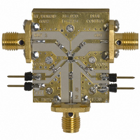
... ILLUSTRATION OF THE TEST CIRCUIT ASSEMBLED ON EVALUATION BOARD V cont2 Vc1 INPUT IN Vc2 V cont1 USING THE NEC EVALUATION BOARD SYMBOL VALUES C1, C2, C3 100 pF C4, C5 1,000 pF 6pin L2MM SPDT OUTPUT2 OUT 1 OUT 2 OUTPUT1 ...
Page 7
PACKAGE DIMENSIONS 6-PIN LEAD-LESS MINIMOLD (1511) (UNIT: mm) Remark ( ) : Reference value (Top View) (Bottom View) 1.1±0.1 0.2±0.1 0.9±0.1 1.3±0.05 ...
Page 8
... Frequency f (GHz) Remark The graphs indicate nominal characteristics. Caution These characteristics values include the losses of the NEC evaluation board blocking capacitors = 100 pF, unless otherwise specified) 1: -0.565 dB 1.0 GHz 2: -0.695 dB 1.5 GHz 3: -0.858 dB 2.0 GHz 4: -0.984 dB 2 ...
Page 9
INPUT-OUTPUT1 ISOLATION vs. FREQUENCY -10 - -40 -50 0.5 1.0 1.5 2.0 Frequency f (GHz) INPUT-OUTPUT1 INPUT RETURN LOSS vs. FREQUENCY -10 -20 1 ...
Page 10
OUTPUT POWER vs. INPUT POWER GHz Input Power P in Remark The graphs indicate nominal characteristics (dBm) ...
Page 11
... Life Support Applications These NEC products are not intended for use in life support devices, appliances, or systems where the malfunction of these products can reasonably be expected to result in personal injury. The customers of CEL using or selling these products for use in such applications their own risk and agree to fully indemnify CEL for all damages resulting from such improper use or sale ...
Page 12
Subject: Compliance with EU Directives CEL certifies, to its knowledge, that semiconductor and laser products detailed below are compliant with the requirements of European Union (EU) Directive 2002/95/EC Restriction on Use of Hazardous Substances in electrical and electronic equipment (RoHS) ...