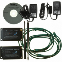
CN4490-1000-SP Laird Technologies, CN4490-1000-SP Datasheet

CN4490-1000-SP
Specifications of CN4490-1000-SP
Related parts for CN4490-1000-SP
CN4490-1000-SP Summary of contents
Page 1
V 1 ...
Page 2
Technical Support: Sales: Phone: 800.492.2320 E-mail: support@aerocomm.com Web: www.aerocomm.com/support Phone: 800.492.2320 E-mail: sales@aerocomm.com Web: www.aerocomm.com ...
Page 3
Document Information Copyright © 2008 AeroComm, Inc. All rights reserved. The information contained in this manual and the accompanying software programs are copyrighted and all rights are reserved by AeroComm, Inc. AeroComm, Inc. reserves the right to make periodic modifications ...
Page 4
Revision Description Version 1.0 12/27/07 - Initial release version ...
Page 5
CONNEXNET RF TRANSCEIVER 1 ConnexNet Features 1 Overview 1 SPECIFICATIONS 2 HARDWARE INTERFACE 3 LAN Port (RJ-45 connector) 4 Power-over-Ethernet 4 Auto MDI/MDIX Interface 4 CONFIGURATION UTILITY 5 Overview 5 Software Installation ...
Page 6
ONNEX ET AeroComm’s new ConnexNet RF transceiver is a Frequency-Hopping Spread Spectrum (FHSS) radio designed for license free operation in the 900 MHz ISM band. Requiring no additional FCC licensing in the Americas, OEMs can easily ...
Page 7
S PECIFICATIONS Interface Connector RF Connector Serial Interface Data Rate ...
Page 8
H I ARDWARE NTERFACE Ethernet Activity LED RJ45 Connector Ethernet Link LED Status LEDs RPSMA Antenna Connector Pwr Link ...
Page 9
...
Page 10
C ONFIGURATION Aerocomm provides an easy to use Configuration utility to program and test the ConnexNet. The GUI based software is compatible with Microsoft® Windows 95, 98, 2000, ME, NT, & XP. ...
Page 11
The PC Settings page is ...
Page 12
The software can control up to (2) COM ports or TCP/IP ports, including virtual COM ports, which physically map to USB or ...
Page 13
Located at the bottom of the software, the status bar ...
Page 14
The Configure page is a GUI representation of the 256 byte EEPROM contents within the radio. The same data is shown in a full hexadecimal dump of ...
Page 15
After making ...
Page 16
An EEPROM can be saved to a file using the Save to File button. This allows for the current state of the EEPROM to be restored at a later time ...
Page 17
The ...
Page 18
The Range Test page allows packets of data to be sent between two radios and reports the numbers of successes and errors ...
Page 19
using two PCs for the test, the software run on both sides should have the second COM ...
Page 20
D S EVICE ETUP The ConnexNet can be setup several different ways; depending on network configuration and specific application needs. Each ConnexNet has an embedded device server which can be configured as a TCP socket or Virtual COM Port. By ...
Page 21
Press the “Configure” button just below the Port field. This will bring up a screen which allows 9 you to change the IP settings and enable/disable DHCP. ...
Page 22
The ‘Choose Destination Location’ screen will appear. Accept the default location. 7 The ‘Setup Status’ screen appears while files are being copied. 8 www.aerocomm.com ...
Page 23
the ‘Username & Password Required’ screen, create a User Name and Password for use with 9 the COM port User Name & Password are ...
Page 24
Select Raw mode, set Port No to 2101. 11 After setup is complete, press the Done button to finish the installation completion screen will appear. You will be prompted to reboot the computer. Select Yes want ...
Page 25
...
Page 26
’ ...
Page 27
The second field listed is labeled IP address with a default setting of 192.168.2.1. Replace the 6 default setting with the IP address shown in the DHCP ...
Page 28
Select TCP/IP from the Connect using drop-down. Type in the IP address you noted from the 9 Auto Discovery Manager. Set the port to 23. Press OK to continue. www.aerocomm.com ...
Page 29
When prompted, login to the device. 10 Login: admin Password: admin ...
Page 30
At the prompt, type the following command: #set ip eth0 dhcp-client disable 11 Wait for an OK response the prompt, type the following command: #set ip eth0 ip 10.16.202.81 13 Note: In this example, the desired static IP ...
Page 31
the prompt, type the following command: #save 23 Repeat for second (and additional radios). 24 ...
Page 32
When you enable bridging, the serial-to-ethernet interface is disabled and ...
Page 33
When prompted, login to the device. 3 Login: admin Password: admin ...
Page 34
At the prompt, type the following command: #show bridge configuration 4 Check to make sure that the device reports that bridge is enabled. 5 Wait for an OK response the prompt, type the following command: #set bridge disable ...
Page 35
Repeat for second (and additional radios Technical Support is available Monday ...


