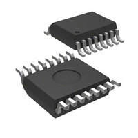
MICRF213AYQS Micrel Inc, MICRF213AYQS Datasheet

MICRF213AYQS
Specifications of MICRF213AYQS
Available stocks
Related parts for MICRF213AYQS
MICRF213AYQS Summary of contents
Page 1
... Frequency from 300MHz to 350MHz • Low current consumption: 3.9mA @ 315MHz, continuous on data rates to 7.2kbps (Manchester Encoded) • Analog RSSI Output • filter required • Excellent selectivity and noise rejection • Low external part count Ordering Information Part Number MICRF213AYQS U1 MICRFAYQS 1 RO1 2 GNDRF 3 ANT 4 GNDRF 5 +3 ...
Page 2
... Reference resonator input connection to Colpitts oscillator stage, 7pF, in parallel with low resistance MOS switch-to-GND, during normal operation. Driven by startup excitation circuit during the internal startup control sequence. May 2007 RO1 1 16 RO2 GNDRF 2 15 ANT 3 14 GNDRF 4 13 VDD SEL0 7 10 SHDN 8 9 MICRF213AYQS 2 MICRF213 NC RSSI CAGC CTH SEL1 DO GND M9999-052307-A (408) 944-0800 ...
Page 3
Micrel, Inc. Absolute Maximum Ratings Supply Voltage (V ) .................................................+5V DD Input Voltage .............................................................+5V Junction Temperature ......................................... +150ºC Lead Temperature (soldering, 10sec.) .................. 260°C Storage Temperature (T ) .....................-65°C to +150°C S Maximum Receiver Input Power ........................+10dBm (3) EDS Rating ...
Page 4
Micrel, Inc. Symbol Parameter Demodulator CTH Source Impedance CTH Leakage Current Demodulator Filter Bandwidth @ 315MHz (Programmable, see application section) Digital / Control Functions DO pin output current Output rise and fall times RSSI RSSI DC Output Voltage Range RSSI ...
Page 5
Micrel, Inc. Typical Characteristics Sensitivity Graphs RSSI Voltage vs. Input Power 2.5 2.0 1.5 1.0 0.5 0 -120 -100 -80 -60 -40 INPUT POWER (dBm) Sesitivity vs. BER -106 -108 -110 -112 -114 -116 1.00E-04 1.00E-03 1.00E-02 1.00E-01 BER May ...
Page 6
Micrel, Inc. Functional Diagram RF ANT Amp VDD f LO VSS SEL Synthesizer SEL SQUELCH Reference and Control SHDN Functional Description Figure 1. Simplified Block Diagram the basic structure of the MICRF213 made of three sub- ...
Page 7
Micrel, Inc. Detector and Programmable Low-Pass Filter The demodulation starts with the detector removing the carrier from the IF signal. Post detection, the signal becomes base band information. The programmable low-pass filter further enhances the base band information. There are ...
Page 8
Micrel, Inc. Application Information ANT1 Helical PCB Antenna Pattern C9 ANT2 C3 1.8pF J2 (np)SMA 6.8pF 39nH 5% 68nH 5% The MICRF213 can be fully tested by using one of the many evaluation boards designed by Micrel ...
Page 9
Micrel, Inc. Please keep in mind that these suggested values may be different if the layout is not exactly the same as the one depicted here. Freq (MHz) C3 (pF) L2 (nH) 303.825 1.8 72 315 1.8 68 345 1.8 ...
Page 10
Micrel, Inc. the top layer close to the REFOSC pins RO1 and RO2. When care is not taken in the layout, and crystals from other vendors are used, the oscillator may take longer times to start as well as the ...
Page 11
Micrel, Inc. For best results, the values should always be optimized for the data pattern used. As the baud rate increases, the capacitor values decrease. Table 9 shows suggested values for Manchester Encoded data at 50% duty cycle. SEL0 SEL1 ...
Page 12
Micrel, Inc. Figure 10. Time-to-Good Data After Shut Down Cycle, Room Temperature May 2007 12 MICRF213 M9999-052307-A (408) 944-0800 ...
Page 13
Micrel, Inc. PCB Considerations and Layout Figure 11 through 16 show some of the printed circuit layers for the QR211HE1 board. The MICRF213 shares the exact same board with different component values. Use the Gerber files provided (downloadable from Micrel ...
Page 14
Micrel, Inc. Figure 14. QR211/213HE1 Bottom Silkscreen Layer, Mirror Image May 2007 Figure 13. QR211/213HE1 Top Silkscreen Layer Figure 15. QR211/213HE1 Dimensions 14 MICRF213 M9999-052307-A (408) 944-0800 ...
Page 15
... J3 L1 Coilcraft L2 Coilcraft L3 Coilcraft R1,R2 R3 Vishay Y1 HCM49 HIB Y1A HC49 HIB U1 MICRF213AYQS Micrel Inc. Notes: 1. Murata: www.murata.com 2. Vishay: www.vishay.com 3. Coilcraft: www.coilcraft.com 4. ACT1: www.act1.com 5. HIB: www.hib.com.br 6. Micrel, Inc.: www.micrel.com May 2007 Description Helical PCB Antenna Pattern (np)50Ω Ant (1) 1.8pF, 0402/0603 (1) (2) / Vishay 4.7µ ...
Page 16
Micrel, Inc. Package Information MICREL, INC. 2180 FORTUNE DRIVE SAN JOSE, CA 95131 USA TEL +1 (408) 944-0800 FAX +1 (408) 474-1000 WEB http:/www.micrel.com The information furnished by Micrel in this data sheet is believed to be accurate and reliable. ...


