ALPHA-RX433S RF Solutions, ALPHA-RX433S Datasheet - Page 19
ALPHA-RX433S
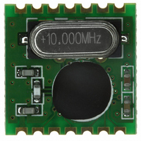
Manufacturer Part Number
ALPHA-RX433S
Description
RECEIVER RF ALPHA 5.4V 433MHZ
Manufacturer
RF Solutions
Datasheet
1.ALPHA-RX433S.pdf
(20 pages)
Specifications of ALPHA-RX433S
Frequency
433MHz
Sensitivity
-100dBm
Data Rate - Maximum
115.2kbps
Modulation Or Protocol
FM, FSK
Current - Receiving
11mA
Data Interface
PCB, Surface Mount
Antenna Connector
PCB, Surface Mount
Voltage - Supply
2.2 V ~ 5.4 V
Operating Temperature
-40°C ~ 85°C
Package / Case
Module
Lead Free Status / RoHS Status
Lead free / RoHS Compliant
Features
-
Applications
-
Memory Size
-
Available stocks
Company
Part Number
Manufacturer
Quantity
Price
Company:

Part Number:
ALPHA-RX433S
Manufacturer:
RF Solutions
Quantity:
135


DSALPHA-4
The read command starts with a zero, whereas all other control commands start with a one. Therefore,
after receiving the first bit of the control command the module identifies it as a read command. So as the
first bit of the command is received, the receiver starts to clock out the status bits on the SDO output as
follows::-
FIFO IT
FFOV
WK-UP
LBD
FFEM
DRSSI
DQD
CRL
ATGL
ASAME
OFFS6, 4-0
Note: The FIFO IT bit behaves like a status bit, but generates nIRQ pulse if active. To check whether
there is a sufficient amount of data in
the FIFO, the SDO output can be tested. In extreme speed critical applications, it can be useful to read
only the first four bits (FIFO IT - LBD)
to clear the FFOV, WK-UP, and LBD bits. During the FIFO access the fSCK cannot be higher than fref /4,
where fref is the crystal oscillator
frequency. If the FIFO is read in this mode the nFFS input must be connected to logic high level.
FIFO Buffered Data Read
In this operating mode, incoming data are clocked into a 16 bit FIFO buffer. The receiver starts to fill up
the FIFO when the Valid Data
Indicator (VDI) bit and/or the synchron word recognition circuit indicates potentially real incoming data.
This prevents the FIFO from being
filled with noise and overloading the external microcontroller.
For further details see the Receiver Setting Command and the Output and FIFO Command.
Polling Mode:
The nFFS signal selects the buffer directly and its content could be clocked out through pin SDO by SCK.
Set the FIFO IT level to 1. In this
case, as long as FFIT indicates received bits in the FIFO, the controller may continue to take the bits
away. When FFIT goes low, no more bits
need to be taken. An SPI read command is also available.
Interrupt Controlled Mode:
The user can define the FIFO level (the number of received bits) which will generate the nFFIT when
exceeded. The status bits report the
changed FIFO status in this case.
13.Status Read Command
Jul 09
Number of the data bits in the FIFO is reached the preprogrammed limit
FIFO overflow
Wake-up timer overflow
Low battery detect, the power supply voltage is below the preprogrammed limit
FIFO is empty
The strength of the incoming signal is above the preprogrammed limit
Data Quality Detector detected a good quality signal
Clock recovery lock
Toggling in each AFC cycle
AFC stabilized (measured twice the same offset value)
Offset value to be added to the value of the Frequency control word
ALPHA RF M
© 2009 RF Solutions Ltd.
ODULES
Page 19
ALPHA-RX
ALPHA-TX
Related parts for ALPHA-RX433S
Image
Part Number
Description
Manufacturer
Datasheet
Request
R

Part Number:
Description:
GaAs IC high linearity positive control SPDT switch DC-2 GHz
Manufacturer:
Alpha Industries
Datasheet:
Part Number:
Description:
PHEMT GaAs IC SPDT switch DC-2.5 GHz
Manufacturer:
Alpha Industries
Datasheet:
Part Number:
Description:
Switch and Attenuator Plastic Packaged PIN Diodes
Manufacturer:
Alpha Industries
Datasheet:
Part Number:
Description:
PHEMT GaAs IC SPDT switch DC-3 GHz
Manufacturer:
Alpha Industries
Datasheet:
Part Number:
Description:
PHEMT GaAs IC SPDT switch DC-2.5 GHz
Manufacturer:
Alpha Industries
Datasheet:
Part Number:
Description:
Two-way 0 power splitter combiner 1.42-1.66 GHz
Manufacturer:
Alpha Industries
Datasheet:
Part Number:
Description:
Hyperabrupt junction tuning varactor
Manufacturer:
Alpha Industries
Datasheet:
Part Number:
Description:
HIP3 variable attenuator 1.7-2 GHz
Manufacturer:
Alpha Industries
Datasheet:
Part Number:
Description:
90 degree hybrid 0.88-0.96 GHz
Manufacturer:
Alpha Industries
Datasheet:
Part Number:
Description:
Low resistance plastic packaged PIN diode
Manufacturer:
Alpha Industries
Datasheet:
Part Number:
Description:
Manufacturer:
Alpha Industries
Datasheet: