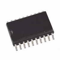
ATA8204P3-TKQY Atmel, ATA8204P3-TKQY Datasheet - Page 6

ATA8204P3-TKQY
Manufacturer Part Number
ATA8204P3-TKQY
Description
IC RCVR ASK/FSK UHF 433MHZ 20SSO
Manufacturer
Atmel
Datasheet
1.ATA8203P3-TKQY.pdf
(46 pages)
Specifications of ATA8204P3-TKQY
Frequency
433MHz
Sensitivity
-115dBm
Data Rate - Maximum
10 kbps
Modulation Or Protocol
ASK, FSK
Applications
General Purpose
Current - Receiving
8.5mA
Data Interface
PCB, Surface Mount
Antenna Connector
PCB, Surface Mount
Features
RSSI Equipped
Voltage - Supply
4.5 V ~ 5.5 V
Operating Temperature
-40°C ~ 85°C
Package / Case
20-SOIC (0.200", 5.30mm Width)
Pin Count
20
Screening Level
Industrial
Lead Free Status / RoHS Status
Lead free / RoHS Compliant
Memory Size
-
Lead Free Status / Rohs Status
Compliant
4. Analog Signal Processing
4.1
4.2
6
IF Filter
Limiting RSSI Amplifier
ATA8203/ATA8204/ATA8205
To determine f
is f
the crystal frequency f
f
f
f
The relationship is designed to achieve the nominal IF frequency of:
f
f
f
The RF input either from an antenna or from an RF generator must be transformed to the RF
input pin LNA_IN. The input impedance of this pin is provided in the electrical parameters. The
parasitic board inductances and capacitances influence the input matching. The RF receiver
ATA8203/ATA8204/ATA8205 exhibits its highest sensitivity if the LNA is power matched.
Because of this, matching to a SAW filter, a 50 or an antenna is easier.
Figure 14-1 on page 32
f
in
characteristics.
The signals coming from the RF front-end are filtered by the fully integrated 4th-order IF filter.
The IF center frequency is:
f
f
f
The nominal bandwidth is 300 kHz for ATA8203 and ATA8204 and 600 kHz for ATA8205.
The subsequent RSSI amplifier enhances the output signal of the IF amplifier before it is fed into
the demodulator. The dynamic range of this amplifier is R
operated within its linear range, the best S/N ratio is maintained in ASK mode. If the dynamic
range is exceeded by the transmitter signal, the S/N ratio is defined by the ratio of the maximum
RSSI output voltage and the RSSI output voltage due to a disturber. The dynamic range of the
RSSI amplifier is exceeded if the RF input signal is approximately 60 dB higher compared to the
RF input signal at full sensitivity.
The S/N ratio is not affected by the dynamic range of the RSSI amplifier in FSK mode because
only the hard limited signal from a high-gain limiting amplifier is used by the demodulator.
The output voltage of the RSSI amplifier (VRSSI) is available at pin RSSI. Using the RSSI output
signal, the signal strength of different transmitters can be distinguished. The usable input power
range P
IF
IF
IF
IF
IF
IF
RF
IF
IF
IF
Table 14-2 on page 32
= f
= f
= f
= 987 kHz for the 315 MHz and B
= 987 kHz for the 433.92 MHz and B
= 947.8 kHz for the 868.3 MHz and B
= 987 kHz for the 315 MHz and B
= 987 kHz for the 433.92 MHz and B
= 947.9 kHz for the 868.3 MHz and B
IF
= 315 MHz, f
= 950 kHz. To achieve a good accuracy of the filter corner frequencies, the filter is tuned by
LO
LO
LO
/318 for the 315 MHz band (ATA8203)
/438 for the 433.92 MHz band (ATA8204)
/915 for the 868.3 MHz band (ATA8205)
Ref
is –100 dBm to –55 dBm.
LO
RF
, the construction of the IF filter must be considered. The nominal IF frequency
= 433.92 MHz or f
XTO
. This means that there is a fixed relationship between f
“Application Circuit” shows a typical input matching network for
is the reference network for the parameters given in the electrical
IF
IF
RF
= 300 kHz (ATA8203)
= 300 kHz (ATA8203)
IF
IF
= 868.3 MHz to 50 . The input matching network shown
IF
IF
= 300 kHz (ATA8204)
= 300 kHz (ATA8204)
= 600 kHz (ATA8205)
= 600 kHz (ATA8205)
RSSI
= 60 dB. If the RSSI amplifier is
9121B–INDCO–04/09
IF
and f
LO
.


