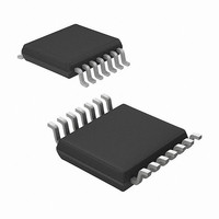
MRF49XA-I/ST Microchip Technology, MRF49XA-I/ST Datasheet - Page 12

MRF49XA-I/ST
Manufacturer Part Number
MRF49XA-I/ST
Description
IC RF TXRX 433/868/915 16-TSSOP
Manufacturer
Microchip Technology
Datasheet
1.MRF49XA-IST.pdf
(102 pages)
Specifications of MRF49XA-I/ST
Package / Case
16-TSSOP
Frequency
433MHz, 868MHz, 915MHz
Data Rate - Maximum
256kbps
Modulation Or Protocol
FHSS, FSK
Applications
Home / Industrial Automation, Remote Access, Security Alarms
Power - Output
7dbm
Sensitivity
-110dBm
Voltage - Supply
2.2 V ~ 3.8 V
Current - Receiving
11mA
Current - Transmitting
15mA
Data Interface
PCB, Surface Mount
Antenna Connector
PCB, Surface Mount
Operating Temperature
-40°C ~ 85°C
Number Of Receivers
1
Number Of Transmitters
2
Wireless Frequency
433 MHz to 915 MHz
Output Power
+ 7 dBm
Operating Supply Voltage
2.5 V, 3.3 V
Maximum Operating Temperature
+ 85 C
Mounting Style
SMD/SMT
Minimum Operating Temperature
- 40 C
Modulation
FHSS, FSK
Lead Free Status / RoHS Status
Lead free / RoHS Compliant
Memory Size
-
Lead Free Status / Rohs Status
Lead free / RoHS Compliant
Other names
579-MRF49XA-1/ST
Available stocks
Company
Part Number
Manufacturer
Quantity
Price
Company:
Part Number:
MRF49XA-I/ST
Manufacturer:
IR
Quantity:
450
Part Number:
MRF49XA-I/ST
Manufacturer:
MICROCHIP/微芯
Quantity:
20 000
TABLE 2-1:
DS70590B-page 10
MRF49XA
Pin
10
11
12
13
14
15
16
9
RFXTL/EXTREF
PIN DESCRIPTION (CONTINUED)
Symbol
INT/DIO
RESET
RSSIO
RFP
RFN
V
Vss
DD
Analog Input/Output Received Signal Strength Indicator Output: The analog
Digital Input/Output Active-low hardware pin. This pin has an open-drain Reset
Digital Input/Output Interrupt: This pin can be configured as an active-low
RF Input/Output
RF Input/Output
Analog Input
Ground
Power
Type
Preliminary
RF Crystal: This pin is connected to a 10 MHz series crystal
or to an external oscillator reference. The crystal is used as a
reference for the PLL which generates the local oscillator
frequency. It is possible to “pull” the crystal to the accurate
frequency by changing the load capacitor value.
External Reference Input: An external reference input, such
as an oscillator, can be connected as a reference source.
Connect the oscillator through a 0.01 μF capacitor.
output with internal pull-up and input buffer. Refer to
Section 3.1 “Reset” for more details.
Ground reference.
Differential RF input/output (+).
Differential RF input/output (-).
RF power supply. Bypass with a capacitor close to the pin.
See Section 2.1 “Power and Ground Pins” for more
details.
RSSI output is used to determine the signal strength. The
response and settling time depends on the external filter
capacitor. Typically, a 4-10 nF capacitor provides optimum
response time for most applications.
external interrupt to the device. If a logic ‘0’ is applied to this
pin, it causes the IRO pin to toggle, signaling an interrupt to
the external microcontroller. The source of interrupt can be
determined by reading the first four bits of STSREG (see
Table 2-4). This pin can be used to wake-up the device from
Sleep.
Data Indicator Output: This pin can be configured to
indicate valid data based on the actual internal settings.
Description
© 2009 Microchip Technology Inc.


