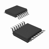
MRF49XA-I/ST Microchip Technology, MRF49XA-I/ST Datasheet - Page 14

MRF49XA-I/ST
Manufacturer Part Number
MRF49XA-I/ST
Description
IC RF TXRX 433/868/915 16-TSSOP
Manufacturer
Microchip Technology
Datasheet
1.MRF49XA-IST.pdf
(102 pages)
Specifications of MRF49XA-I/ST
Package / Case
16-TSSOP
Frequency
433MHz, 868MHz, 915MHz
Data Rate - Maximum
256kbps
Modulation Or Protocol
FHSS, FSK
Applications
Home / Industrial Automation, Remote Access, Security Alarms
Power - Output
7dbm
Sensitivity
-110dBm
Voltage - Supply
2.2 V ~ 3.8 V
Current - Receiving
11mA
Current - Transmitting
15mA
Data Interface
PCB, Surface Mount
Antenna Connector
PCB, Surface Mount
Operating Temperature
-40°C ~ 85°C
Number Of Receivers
1
Number Of Transmitters
2
Wireless Frequency
433 MHz to 915 MHz
Output Power
+ 7 dBm
Operating Supply Voltage
2.5 V, 3.3 V
Maximum Operating Temperature
+ 85 C
Mounting Style
SMD/SMT
Minimum Operating Temperature
- 40 C
Modulation
FHSS, FSK
Lead Free Status / RoHS Status
Lead free / RoHS Compliant
Memory Size
-
Lead Free Status / Rohs Status
Lead free / RoHS Compliant
Other names
579-MRF49XA-1/ST
Available stocks
Company
Part Number
Manufacturer
Quantity
Price
Company:
Part Number:
MRF49XA-I/ST
Manufacturer:
IR
Quantity:
450
Part Number:
MRF49XA-I/ST
Manufacturer:
MICROCHIP/微芯
Quantity:
20 000
reference signal for the PLL. The PLL, in turn, generates
capacitor is programmable from 8.5 pF-16 pF in 0.5 pF
reference for the carrier. An external reference input,
2.5
The MRF49XA has an internal, integrated crystal oscilla-
tor circuit, and therefore, a single RFXTL/EXTREF pin is
used as a crystal oscillator. The crystal oscillator circuit,
with internal loading capacitors, provides a 10 MHz
the local oscillator frequency. It is possible to “pull” the
crystal to the accurate frequency by changing the load
capacitor value. This reduces the external component
count and simplifies the design. The crystal load
steps. Thus, the crystal oscillator circuit can accept a
wide range of crystals from different manufacturers with
different load capacitance requirements. The ability to
vary the load capacitance also helps in fine tuning the
final carrier frequency as the crystal itself is the PLL
such as an oscillator, can be connected as a reference
source. The oscillator can be connected through a
0.01 μF capacitor. Choosing better crystal results in a
lesser TX to RX frequency offset and smaller deviation in
baseband bandwidth. Hence, the recommended crystal
accuracy should be ≤ 40 ppm. Deviation and baseband
bandwidth are discussed in detail in Section 2.8 “Base-
band/Data Filters”. The guidelines for selecting the
appropriate crystal are explained in Section 3.6 “Crystal
Selection Guidelines”.
The transceiver can provide a clock signal through the
Clock Output (CLKOUT) pin to the microcontroller for
accurate timing, and thus, eliminating the need for a
second crystal. This also results in reducing the
component count.
2.6
The Phase Locked Loop (PLL) circuitry determines the
operating frequency of the device. This programmable
PLL synthesizer requires only a single 10 MHz crystal
reference source. The PLL maintains accuracy by
using the on-chip crystal controlled reference oscillator
and provides maximum flexibility in performance to the
designers. It is possible to change the crystal to the
accurate frequency by changing the load capacitor
value. The RF stability can be controlled by selecting a
crystal with specifications which satisfy the application
and by providing the functions required to generate the
carriers, and by tuning each of the bands. For more
details, see Section 3.6 “Crystal Selection Guide-
lines”. The PLL’s high resolution allows the use of
multiple channels in any of the bands. The on-chip PLL
is able to perform manual and automatic calibration to
compensate for the changes in temperature or
operating voltage.
DS70590B-page 12
MRF49XA
RFXTL/EXTREF and CLKOUT Pins
Phase Locked Loop
Preliminary
2.7
The PLL in MRF49XA is capable of performing auto-
matic fine adjustment for the carrier frequency by using
an integrated Automatic Frequency Control (AFC)
feature. The receiver uses the AFC feature to minimize
the frequency offset between the TX/RX signals in
discrete steps, which gives the advantage of:
• Narrower receiver bandwidth for increased
• Higher data rates can be achieved
• Usability of any locally available, low-accuracy
The MRF49XA can be programmed to automatically
control the frequency or can be manually activated by
a strobe signal.
2.8
The Baseband Filters (BBFs) are user-programmable.
The receiver bandwidth can be set by programming the
bandwidth of the baseband filters. The receiver, when
programmed, is set up according to the characteristics
of the signal to be received. The baseband receiver has
several programming options to optimize the communi-
cation for a variety of applications. The programmable
functions are as follows:
• Baseband Analog Filter
• Baseband Digital Filter
• Receive Bandwidth
• Receive Data Rate
• Clock Recovery
The output data filtering can be performed by using an
external capacitor or by using a digital filter based on
the user application. The RCLKOUT/FCAP/FINT pin in
MRF49XA provides the raw baseband data if config-
ured as a configuration filter. It can be used by the host
microcontroller to perform the data recovery.
2.9
The Clock Recovery Circuit (CLKRC) is used to render
a synchronized clock source to recover the data using
an external microcontroller. The clock recovery circuit
works by sampling the preamble on the received data.
The preamble contains a sequence of 1 and 0 for the
CLKRC to properly extract the data timing. In Slow
mode, the CLKRC requires more sampling (12 to 16
bits), and hence, has a longer settling time before lock-
ing. In Fast mode, it uses less samples (6 to 8 bits)
before locking, and thereby, the settling time is short
which makes timing accuracy less critical. The
RCLKOUT/FCAP/FINT
recovered from the incoming data if the baseband filter
is configured as a digital filter.
sensitivity can be achieved
and inexpensive crystals can be used
Automatic Frequency Control
Baseband/Data Filters
Clock Recovery Circuit
© 2009 Microchip Technology Inc.
pin
provides
the
clock


