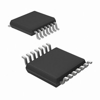
MRF49XA-I/ST Microchip Technology, MRF49XA-I/ST Datasheet - Page 60

MRF49XA-I/ST
Manufacturer Part Number
MRF49XA-I/ST
Description
IC RF TXRX 433/868/915 16-TSSOP
Manufacturer
Microchip Technology
Datasheet
1.MRF49XA-IST.pdf
(102 pages)
Specifications of MRF49XA-I/ST
Package / Case
16-TSSOP
Frequency
433MHz, 868MHz, 915MHz
Data Rate - Maximum
256kbps
Modulation Or Protocol
FHSS, FSK
Applications
Home / Industrial Automation, Remote Access, Security Alarms
Power - Output
7dbm
Sensitivity
-110dBm
Voltage - Supply
2.2 V ~ 3.8 V
Current - Receiving
11mA
Current - Transmitting
15mA
Data Interface
PCB, Surface Mount
Antenna Connector
PCB, Surface Mount
Operating Temperature
-40°C ~ 85°C
Number Of Receivers
1
Number Of Transmitters
2
Wireless Frequency
433 MHz to 915 MHz
Output Power
+ 7 dBm
Operating Supply Voltage
2.5 V, 3.3 V
Maximum Operating Temperature
+ 85 C
Mounting Style
SMD/SMT
Minimum Operating Temperature
- 40 C
Modulation
FHSS, FSK
Lead Free Status / RoHS Status
Lead free / RoHS Compliant
Memory Size
-
Lead Free Status / Rohs Status
Lead free / RoHS Compliant
Other names
579-MRF49XA-1/ST
Available stocks
Company
Part Number
Manufacturer
Quantity
Price
Company:
Part Number:
MRF49XA-I/ST
Manufacturer:
IR
Quantity:
450
Part Number:
MRF49XA-I/ST
Manufacturer:
MICROCHIP/微芯
Quantity:
20 000
TABLE 3-2:
FIGURE 3-11:
3.13.1
The DIO signal response time setting is configured
through RXCREG and has the following modes of
operation:
• Normal Mode
• Slow Mode
• Medium Mode
• Fast Mode
These operation modes are configurable through
BBFCREG.
In Medium mode, the DIO signal is active when the
CR_LOCK and the DRSSI or the DQI signals are high.
The data indicator output goes low when either the
CR_LOCK turns inactive, or the DRSSI or DQI signals
go low. For more details on DQI, see Section 3.11
“Data Quality Indicator”.
DS70590B-page 58
MRF49XA
RSSI Threshold
Reserved
Reserved
RELATIONSHIP BETWEEN RSSI
AND CLOCK RECOVERY
-103
-73
-79
-85
-91
-97
-112
DIGITAL RSSI THRESHOLD LEVELS
INPUT POWER
-102
-92
DRSSIT2
VS
1
1
1
1
0
0
0
0
. ANALOG RSSI VOLTAGE
Input Power (dBm)
-82
Preliminary
-72
3.13.2
The Keep Offset mode of automatic configuration of
AFC (i.e., AUTOMS1 = 1, AUTOMS0 = 1) is recom-
mended to be used when a receiver operates with only
one transmitter. After a complete measuring cycle, the
measured value is kept independent from the state of
the DIO signal. In this mode, the DRSSI limit should be
carefully selected to minimize the range hysteresis.
The registers associated with RSSI are:
• STSREG (see Register 2-1)
• GENCREG (see Register 2-2)
• RXCREG (see Register 2-7)
• PMCREG (see Register 2-13)
DRSSIT1
1
1
0
0
1
1
0
0
-62
RELATIONSHIP BETWEEN RSSI
AND AFC
-52
© 2009 Microchip Technology Inc.
-42
DRSSIT0
1.2
1
0.8
0.6
0.4
0.2
0
1
0
1
0
1
0
1
0


