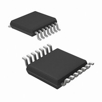
MRF49XA-I/ST Microchip Technology, MRF49XA-I/ST Datasheet - Page 81

MRF49XA-I/ST
Manufacturer Part Number
MRF49XA-I/ST
Description
IC RF TXRX 433/868/915 16-TSSOP
Manufacturer
Microchip Technology
Datasheet
1.MRF49XA-IST.pdf
(102 pages)
Specifications of MRF49XA-I/ST
Package / Case
16-TSSOP
Frequency
433MHz, 868MHz, 915MHz
Data Rate - Maximum
256kbps
Modulation Or Protocol
FHSS, FSK
Applications
Home / Industrial Automation, Remote Access, Security Alarms
Power - Output
7dbm
Sensitivity
-110dBm
Voltage - Supply
2.2 V ~ 3.8 V
Current - Receiving
11mA
Current - Transmitting
15mA
Data Interface
PCB, Surface Mount
Antenna Connector
PCB, Surface Mount
Operating Temperature
-40°C ~ 85°C
Number Of Receivers
1
Number Of Transmitters
2
Wireless Frequency
433 MHz to 915 MHz
Output Power
+ 7 dBm
Operating Supply Voltage
2.5 V, 3.3 V
Maximum Operating Temperature
+ 85 C
Mounting Style
SMD/SMT
Minimum Operating Temperature
- 40 C
Modulation
FHSS, FSK
Lead Free Status / RoHS Status
Lead free / RoHS Compliant
Memory Size
-
Lead Free Status / Rohs Status
Lead free / RoHS Compliant
Other names
579-MRF49XA-1/ST
Available stocks
Company
Part Number
Manufacturer
Quantity
Price
Company:
Part Number:
MRF49XA-I/ST
Manufacturer:
IR
Quantity:
450
Part Number:
MRF49XA-I/ST
Manufacturer:
MICROCHIP/微芯
Quantity:
20 000
TABLE 5-4:
Note 1:
© 2009 Microchip Technology Inc.
Receiver Sensitivity
Maximum RF Input
Power
RF Input Capacitance
Receiver Spurious
Emission
Receiver BW
RSSI Range
RSSI Error
RSSI Power Supply
Dependency
Filter Capacitor for
Analog RSSI
RSSI Programmable
Level Steps
Digital RSSI
Response Time
Input IP3
IIP3
(LNA – 6 dB gain)
IIP3
(LNA – 6 dB gain)
FSK Bit Rate
FSK Bit Rate
AFC Locking Range
Parameters
2:
Typical Values: T
BER = 10E – 3, BW = 67 kHz, Δf = 30 kHz, Baud Rate = 1.2 kbps, digital filter with AFC disabled.
RECEIVER AC CHARACTERISTICS
433 MHz band
868 MHz band
915 MHz band
LNA: High Gain
Mode 0
Mode 1
Mode 2
Mode 3
Mode 4
Mode 5
When input signal level is lower than
-54 dBm and greater than -100 dBm
Until the RSSI signal goes high after
the input signal exceeds the
preprogrammed limit,
CARRSI = 4.7 nF
In band interferers in high bands
(868 MHz, 915 MHz)
In band interferers in low band
(433 MHz)
Out of band interferers,
l f-f
With internal digital filters supported
by design
With internal analog filters supported
by design
Δf
signal
fsk
O
A
: FSK deviation in the received
l > 4 MHz
= 25°C, V
Condition
(2)
(2)
(2)
DD
—
—
—
—
—
—
= 3.3V, Local Oscillator Frequency = 2.445 GHz.
Preliminary
(1)
Min
0.6
—
—
—
—
—
—
—
—
—
—
—
—
—
—
—
—
—
—
—
—
—
0
1
0.8 – Δf
-109
-112
-110
Typ
+35
134
200
270
340
400
500
-21
-15
-12
67
—
—
46
±6
—
—
—
1
6
fsk
MRF49XA
115.2
Max
256
-60
—
—
—
—
—
—
—
—
—
—
—
—
—
—
—
—
—
—
—
—
—
DS70590B-page 79
mV/V
dBm
dBm
dBm
dBm
dBm
dBm
dBm
dBm
kbps
kbps
Unit
kHz
kHz
kHz
kHz
kHz
kHz
dB
dB
dB
pF
nF
μs
—


