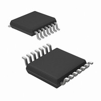
MRF49XA-I/ST Microchip Technology, MRF49XA-I/ST Datasheet - Page 83

MRF49XA-I/ST
Manufacturer Part Number
MRF49XA-I/ST
Description
IC RF TXRX 433/868/915 16-TSSOP
Manufacturer
Microchip Technology
Datasheet
1.MRF49XA-IST.pdf
(102 pages)
Specifications of MRF49XA-I/ST
Package / Case
16-TSSOP
Frequency
433MHz, 868MHz, 915MHz
Data Rate - Maximum
256kbps
Modulation Or Protocol
FHSS, FSK
Applications
Home / Industrial Automation, Remote Access, Security Alarms
Power - Output
7dbm
Sensitivity
-110dBm
Voltage - Supply
2.2 V ~ 3.8 V
Current - Receiving
11mA
Current - Transmitting
15mA
Data Interface
PCB, Surface Mount
Antenna Connector
PCB, Surface Mount
Operating Temperature
-40°C ~ 85°C
Number Of Receivers
1
Number Of Transmitters
2
Wireless Frequency
433 MHz to 915 MHz
Output Power
+ 7 dBm
Operating Supply Voltage
2.5 V, 3.3 V
Maximum Operating Temperature
+ 85 C
Mounting Style
SMD/SMT
Minimum Operating Temperature
- 40 C
Modulation
FHSS, FSK
Lead Free Status / RoHS Status
Lead free / RoHS Compliant
Memory Size
-
Lead Free Status / Rohs Status
Lead free / RoHS Compliant
Other names
579-MRF49XA-1/ST
Available stocks
Company
Part Number
Manufacturer
Quantity
Price
Company:
Part Number:
MRF49XA-I/ST
Manufacturer:
IR
Quantity:
450
Part Number:
MRF49XA-I/ST
Manufacturer:
MICROCHIP/微芯
Quantity:
20 000
TABLE 5-7:
Note 1:
© 2009 Microchip Technology Inc.
Transmitter Switch On Time
Receiver Switch On Time
Transmitter to Receiver Switch
Time
Receiver to Transmitter Switch
Time
Crystal Load Capacitance (See
Crystal Selection Guide)
Crystal Oscillator Start-up Time
Internal POR Time-out
Wake-up Timer Clock Accuracy
Digital Input Capacitance
Digital Output Rise/Fall Time
2:
3:
Typical Values: T
The crystal oscillator start-up time depends on the capacitance seen by the oscillator. Low capacitance and
low-ESR crystal are recommended with low parasitic PCB layout design.
During the Power-on Reset period, commands are not accepted by the chip. In case of Software Reset (see
WTSREG (Register 2-14)), the Reset time-out is typically 0.25 ms.
Parameters
OTHER TIMING PARAMETERS AC CHARACTERISTICS
A
= 25°C, V
Synthesizer off, crystal oscillator
on with 10 MHz step
Synthesizer off, crystal oscillator
on with 10 MHz step
Synthesizer and crystal oscillator
on during TX/RX change with
10 MHz step
Synthesizer and crystal oscillator
on during RX/TX change with
10 MHz step
Programmable in 0.5 pF steps,
tolerance ±10%
Default capacitance bank setting,
crystal ESR < 50Ω. Crystal load
capacitance = 16 pF.
After V
final value
Crystal oscillator must be enabled
to ensure proper calibration at the
start-up
15 pF pure capacitive load
DD
DD
= 3.3V.
(2)
has reached 90% of the
(3)
Condition
Preliminary
—
(2)
Min
8.5
—
—
—
—
—
—
—
—
—
(1)
Typ
250
250
150
150
±10
—
—
—
—
2
MRF49XA
Max
100
16
10
—
—
—
—
—
DS70590B-page 81
7
2
Unit
ms
ms
pF
pF
μs
μs
μs
μs
ns
%


