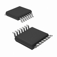
MRF49XA-I/ST Microchip Technology, MRF49XA-I/ST Datasheet - Page 98

MRF49XA-I/ST
Manufacturer Part Number
MRF49XA-I/ST
Description
IC RF TXRX 433/868/915 16-TSSOP
Manufacturer
Microchip Technology
Datasheet
1.MRF49XA-IST.pdf
(102 pages)
Specifications of MRF49XA-I/ST
Package / Case
16-TSSOP
Frequency
433MHz, 868MHz, 915MHz
Data Rate - Maximum
256kbps
Modulation Or Protocol
FHSS, FSK
Applications
Home / Industrial Automation, Remote Access, Security Alarms
Power - Output
7dbm
Sensitivity
-110dBm
Voltage - Supply
2.2 V ~ 3.8 V
Current - Receiving
11mA
Current - Transmitting
15mA
Data Interface
PCB, Surface Mount
Antenna Connector
PCB, Surface Mount
Operating Temperature
-40°C ~ 85°C
Number Of Receivers
1
Number Of Transmitters
2
Wireless Frequency
433 MHz to 915 MHz
Output Power
+ 7 dBm
Operating Supply Voltage
2.5 V, 3.3 V
Maximum Operating Temperature
+ 85 C
Mounting Style
SMD/SMT
Minimum Operating Temperature
- 40 C
Modulation
FHSS, FSK
Lead Free Status / RoHS Status
Lead free / RoHS Compliant
Memory Size
-
Lead Free Status / Rohs Status
Lead free / RoHS Compliant
Other names
579-MRF49XA-1/ST
Available stocks
Company
Part Number
Manufacturer
Quantity
Price
Company:
Part Number:
MRF49XA-I/ST
Manufacturer:
IR
Quantity:
450
Part Number:
MRF49XA-I/ST
Manufacturer:
MICROCHIP/微芯
Quantity:
20 000
Phase Locked Loop (PLL)............................................. 12, 47
Pin Description ...................................................................... 9
Pin Diagram .......................................................................... 2
Pins
Power Amplifier (PA)........................................................... 11
Power and Low Noise Amplifiers ........................................ 46
Power Management ............................................................ 59
Power-Saving Modes
Programmable Synchronous Byte ...................................... 57
R
Reader Response ............................................................... 98
Receive FIFO ...................................................................... 15
Receive Signal Strength Indicator (RSSI) ........................... 13
Received Signal Strength Indicator (RSSI) ......................... 57
Recommended Operating Conditions ................................. 78
Recovery Clock Output ......................................................... 9
Register Map....................................................................... 17
Registers
DS70590B-page 96
MRF49XA
CLKOUT ....................................................................... 9
CS ................................................................................. 9
DATA ............................................................................ 9
FSK/DATA/FSEL .......................................................... 9
INT/DIO ....................................................................... 10
IRO................................................................................ 9
RCLKOUT/FCAP/FINT ................................................. 9
RESET ........................................................................ 10
RFN............................................................................. 10
RFP ............................................................................. 10
RFXTL/EXTREF ......................................................... 10
RSSIO ......................................................................... 10
SCK............................................................................... 9
SDI ................................................................................ 9
SDO .............................................................................. 9
V
V
Low Battery Voltage Detector ..................................... 14
Low Duty Cycle Mode ................................................. 14
Wake-up Timer ........................................................... 14
AFCCREG (Automatic Frequency Control
BBFCREG (Baseband Filter Configuration)................ 29
BCSREG (Battery Threshold Detect and
CFSREG (Center Frequency Value Set) .................... 26
DCSREG (Duty Cycle Value Set) ............................... 39
DRSREG (Data Rate Value Set) ................................ 35
FIFORSTREG (FIFO and Reset Mode
GENCREG (General Configuration) ........................... 20
PLLCREG (PLL Configuration) ................................... 41
PMCREG (Power Management Configuration) .......... 36
RXCREG (Receive Control)........................................ 27
RXFIFOREG (Receiver FIFO Read)........................... 31
STSREG (STATUS Read) .......................................... 18
SYNBREG (Synchronous Byte Configuration) ........... 34
TXBREG (Transmit Byte)............................................ 25
TXCREG (Transmit Configuration) ............................. 23
WTSREG (Wake-up Timer Value Set)........................ 38
DD
SS
.............................................................................. 10
.............................................................................. 10
Configuration) ..................................................... 21
Clock Output Value Set) ..................................... 40
Configuration) ..................................................... 32
Preliminary
Reset
Reset Mode Selection......................................................... 33
RESET Pin.......................................................................... 11
Revision History.................................................................. 93
RF Crystal........................................................................... 10
RF Transmitter Matching .................................................... 72
RF/Analog Features.............................................................. 1
RX FIFO Buffered Data Read............................................. 68
RX-TX Frequency Alignment Method ................................. 70
S
Schematics
Serial Peripheral Interface (SPI) ......................................... 15
Sleep, Wake-up and Battery Operations ............................ 63
SPI
Synchronous Character Selection ...................................... 33
T
Timing Diagrams
Transmit Register ............................................................... 14
TX Register Buffered Data Transmission ........................... 64
Typical Applications .............................................................. 1
V
V
W
Wake-up Timer ................................................................... 14
WWW Address ................................................................... 97
WWW, On-Line Support ....................................................... 3
DD
Line Filtering................................................................ 45
Power Glitch Reset ..................................................... 44
Power-on Reset .......................................................... 43
RESET Pin ................................................................. 45
Software Reset ........................................................... 45
MRF49XA ................................................................... 74
Timing Specification.................................................... 82
FIFO Read with FINT Polling...................................... 69
FSK Modulated Deviation (Max. TX to RX Offset)...... 55
Low-Power Duty Cycle Mode Sequence .................... 62
Multiple Byte Write with Transmit Register ................. 67
Power-on Reset Example ........................................... 43
Receiver FIFO Read................................................... 68
Sensitive Reset Disabled............................................ 45
Sensitive Reset Enabled............................................. 44
SPI .............................................................................. 82
STSREG Read Sequence .......................................... 91
TX Register Usage ..................................................... 67
© 2009 Microchip Technology Inc.


