MRF24WB0MA/RM Microchip Technology, MRF24WB0MA/RM Datasheet - Page 26
MRF24WB0MA/RM
Manufacturer Part Number
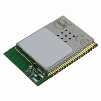
MRF24WB0MA/RM
Description
TXRX RF 2.4GHZ PCB ANT 802.11B
Manufacturer
Microchip Technology
Specifications of MRF24WB0MA/RM
Frequency
2.4GHz
Data Rate - Maximum
1Mbps
Modulation Or Protocol
802.11 b
Applications
ISM
Power - Output
10dBm
Sensitivity
-91dBm
Voltage - Supply
2.7 V ~ 3.6 V
Current - Receiving
85mA
Current - Transmitting
154mA
Data Interface
PCB, Surface Mount
Antenna Connector
On-Board, Trace
Operating Temperature
0°C ~ 70°C
Package / Case
Module
Wireless Frequency
2.4 GHz
Interface Type
SPI, JTAG
Board Size
21 mm x 31 mm
Modulation
DSSS
Security
WEP, WPA-PSK, WPA-2-PSK
Operating Voltage
2.7 V to 3.6 V
Antenna
PCB Meander
Operating Temperature Range
0 C to + 70 C
Frequency Rf
2.4GHz
Transmit Power
9mW
Module Interface
SPI, 4-Wire
Modulation Type
DSSS
Data Rate Max
2Mbps
Supply Current
154mA
Supply Voltage Range
2.7V To 3.6V
Frequency Range
2.4GHz
Leaded Process Compatible
Yes
Rohs Compliant
Yes
For Use With/related Products
PIC18, PIC24, dsPIC33, PIC32
Lead Free Status / RoHS Status
Lead free / RoHS Compliant
Memory Size
-
Lead Free Status / Rohs Status
Lead free / RoHS Compliant
Available stocks
Company
Part Number
Manufacturer
Quantity
Price
Company:

Part Number:
MRF24WB0MA/RM
Manufacturer:
MICROCHIP
Quantity:
2 000


MRF24WB0MA/MRF24WB0MB
TABLE 4-4:
Note 1:
TABLE 4-5:
Note 1:
TABLE 4-6:
Note 1:
DS70632A-page 26
Parameters
I
I
I
I
modulated signal at antenna port
I
I
Parameters
Flo
RX Min Input Level Sensitivity, 1Mbps, 8% PER
RX Min Input Level Sensitivity, 2Mbps, 8% PER
RX Max Input Level (Power), 1Mbps, 8% PER
RX Max Input Level (Power), 2Mbps, 8% PER
Parameters
Flo
Average Pout (transmit spectrum mask compliant)
Average Pout gain step resolution from +5 to +10dBm
Average Pout gain step resolution from -5 to +5dbm
Average Pout settled variation
DD
DD
DD
DD
DD
DD
, Hibernate = 3.3V
, Sleep (software enabled)
, Standby (transitional state)
core
core, TX on, +0 dBm
core, TX on, +10 dBm
2:
3:
(2)
Sleep current is current consumed during periods of “standby” between DTIM beacons. The module will
awake 2 mS before a DTIM and turn on its receiver, and possibly its transmitter (if data is available for it).
I
Current Consumption values represent Typical Peak currents, and the measured current conditions were
done with 85% duty cycle modulated signal. Wi-Fi applications typically operate at less than 85% TX duty
cycle. TX current is dependent on such criteria as transmit power setting, and transmit data rate and band-
width being used. RX current is affected by connection distance.
Nominal conditions: 25C, VDD = 3.3V, Flo = 2437 MHz, measurements at antenna port.
Nominal conditions: 25C, VDD = 3.3V, Flo = 2437 MHz, 2 Mbps. modulated signal measured at antenna
port.
, RX on, Receive @-83dBm with 2Mbps
DD
core is current consumed by the part not including the I/O consumption of the SPI port.
CURRENT CONSUMPTION
RECEIVER AC CHARACTERISTICS
TRANSMITTER AC CHARACTERISTICS
(3)
Preliminary
(NOMINAL CONDITIONS: 25C, VDD = 3.3V)
(1)
2412
2412
Min
Min
-0.5
Min
(1)
250
Typ
154
Typ
Typ
+10
115
-91
-88
0.5
1.0
0.1
10
85
-4
-4
(1)
2010 Microchip Technology Inc.
2484
2484
Max
Max
Max
0.5
Units
Units
Units
MHz
dBm
dBm
dBm
dBm
MHz
dBm
mA
mA
mA
mA
µA
µA
dB
dB
dB
Related parts for MRF24WB0MA/RM
Image
Part Number
Description
Manufacturer
Datasheet
Request
R

Part Number:
Description:
Manufacturer:
Microchip Technology Inc.
Datasheet:
Part Number:
Description:
Manufacturer:
Microchip Technology Inc.
Datasheet:
Part Number:
Description:
Manufacturer:
Microchip Technology Inc.
Datasheet:
Part Number:
Description:
Manufacturer:
Microchip Technology Inc.
Datasheet:
Part Number:
Description:
Manufacturer:
Microchip Technology Inc.
Datasheet:
Part Number:
Description:
Manufacturer:
Microchip Technology Inc.
Datasheet:
Part Number:
Description:
Manufacturer:
Microchip Technology Inc.
Datasheet:
Part Number:
Description:
Manufacturer:
Microchip Technology Inc.
Datasheet: