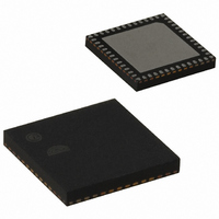
EM357-RTR Ember, EM357-RTR Datasheet - Page 13

EM357-RTR
Manufacturer Part Number
EM357-RTR
Description
IC RF TXRX ZIGBEE 192KB 48QFN
Manufacturer
Ember
Specifications of EM357-RTR
Frequency
2.4GHz
Data Rate - Maximum
250kbps
Modulation Or Protocol
802.15.4 Zigbee
Applications
General Purpose
Power - Output
5dBm
Sensitivity
-100dBm
Voltage - Supply
2.1 V ~ 3.6 V
Current - Receiving
26mA
Current - Transmitting
31mA
Data Interface
PCB, Surface Mount
Memory Size
192kB Flash, 12kB RAM
Antenna Connector
PCB, Surface Mount
Operating Temperature
-40°C ~ 85°C
Package / Case
48-QFN
Lead Free Status / RoHS Status
Lead free / RoHS Compliant
Other names
636-1011-2
Available stocks
Company
Part Number
Manufacturer
Quantity
Price
Company:
Part Number:
EM357-RTR
Manufacturer:
SILICON
Quantity:
3 000
Part Number:
EM357-RTR
Manufacturer:
SILICON
Quantity:
20 000
- Current page: 13 of 245
- Download datasheet (12Mb)
Pin # Signal
36
37
38
39
40
JTMS
SWDIO
PB0
VREF
VREF
IRQA
TRACECLK
(see also Pin 25)
TIM1CLK
TIM2MSK
VDD_PADS
PC1
ADC3
SWO
(see also Pin 33)
TRACEDATA0
VDD_MEM
PC0
JRST
IRQD
1
Direction
I
I/O
I/O
Analog O
Analog I
I
O
I
I
Power
I/O
Analog
O
Power
I/O
High
current
I
I
O
Description
JTAG mode select from debugger
Selected when in JTAG mode (default mode)
JTAG mode is enabled after power-up or by forcing nRESET low
Select Serial Wire mode using the ARM-defined protocol through a
debugger
Internal pull-up is enabled
Serial Wire bidirectional data to/from debugger
Enable Serial Wire mode (see JTMS description)
Select Serial Wire mode using the ARM-defined protocol through a
debugger
Internal pull-up is enabled
Digital I/O
ADC reference output
Enable analog function with GPIO_PBCFGL[3:0]
ADC reference input
Enable analog function with GPIO_PBCFGL[3:0]
Enable reference output with an Ember system function
External interrupt source A
Synchronous CPU trace clock
Enable trace interface in ARM core
Select alternate output function with GPIO_PBCFGL[3:0]
Timer 1 external clock input
Timer 2 external clock mask input
Pads supply (2.1-3.6 V)
Digital I/O
ADC Input 3
Enable analog function with GPIO_PCCFGL[7:4]
Serial Wire Output asynchronous trace output to debugger
Select asynchronous trace interface in ARM core
Enable trace interface in ARM core
Select alternate output function with GPIO_PCCFGL[7:4]
Synchronous CPU trace data bit 0
Select 1-, 2- or 4-wire synchronous trace interface in ARM core
Enable trace interface in ARM core
Select alternate output function with GPIO_PCCFGL[7:4]
1.8 V supply (flash, RAM)
Digital I/O
Either enable with GPIO_DBGCFG[5],
or enable Serial Wire mode (see JTMS description, Pin 35) and disable
TRACEDATA1
JTAG reset input from debugger
Selected when in JTAG mode (default mode, see JTMS description) and
TRACEDATA1 is disabled
Internal pull-up is enabled
Default external interrupt source D
Final
1-8
EM351 / EM357
120-035X-000G
Related parts for EM357-RTR
Image
Part Number
Description
Manufacturer
Datasheet
Request
R

Part Number:
Description:
MODULE EM357 PA/LNA W/ANT TG
Manufacturer:
Ember
Datasheet:

Part Number:
Description:
MODULE EM357 NO PA/LNA W/ANT TG
Manufacturer:
Ember
Datasheet:

Part Number:
Description:
MODULE EM357 NO PA/LNA W/RF CONN
Manufacturer:
Ember
Datasheet:

Part Number:
Description:
MODULE EM357 PA/LNA W/RF CONN
Manufacturer:
Ember
Datasheet:

Part Number:
Description:
IC RF TXRX ZIGBEE 192KB 48QFN
Manufacturer:
Ember
Datasheet:

Part Number:
Description:
KIT DEV EMBER ZIGBEE W/PCWH
Manufacturer:
Custom Computer Services Inc (CCS)

Part Number:
Description:
PROGRAMMER USB FLASH EM250/260
Manufacturer:
Ember
Datasheet:

Part Number:
Description:
IC ZIGBEE SYSTEM-ON-CHIP 40-QFN
Manufacturer:
Ember
Datasheet:

Part Number:
Description:
IC ZIGBEE SYSTEM-ON-CHIP 48-QFN
Manufacturer:
Ember
Datasheet:

Part Number:
Description:
IC RF TXRX ZIGBEE 128KB 48QFN
Manufacturer:
Ember
Datasheet:

Part Number:
Description:
INSIGHT ADAPTER FOR EM2XX
Manufacturer:
Ember
Datasheet:

Part Number:
Description:
PROGRAMMER USB FLASH EM250/260
Manufacturer:
Ember
Datasheet:

Part Number:
Description:
IC ZIGBEE SYSTEM-ON-CHIP 40-QFN
Manufacturer:
Ember
Datasheet:

Part Number:
Description:
IC ZIGBEE SYSTEM-ON-CHIP 48-QFN
Manufacturer:
Ember
Datasheet:

Part Number:
Description:
IC RF TXRX ZIGBEE 128KB 48QFN
Manufacturer:
Ember
Datasheet:


