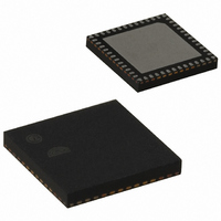
EM357-RTR Ember, EM357-RTR Datasheet - Page 144

EM357-RTR
Manufacturer Part Number
EM357-RTR
Description
IC RF TXRX ZIGBEE 192KB 48QFN
Manufacturer
Ember
Specifications of EM357-RTR
Frequency
2.4GHz
Data Rate - Maximum
250kbps
Modulation Or Protocol
802.15.4 Zigbee
Applications
General Purpose
Power - Output
5dBm
Sensitivity
-100dBm
Voltage - Supply
2.1 V ~ 3.6 V
Current - Receiving
26mA
Current - Transmitting
31mA
Data Interface
PCB, Surface Mount
Memory Size
192kB Flash, 12kB RAM
Antenna Connector
PCB, Surface Mount
Operating Temperature
-40°C ~ 85°C
Package / Case
48-QFN
Lead Free Status / RoHS Status
Lead free / RoHS Compliant
Other names
636-1011-2
Available stocks
Company
Part Number
Manufacturer
Quantity
Price
Company:
Part Number:
EM357-RTR
Manufacturer:
SILICON
Quantity:
3 000
Part Number:
EM357-RTR
Manufacturer:
SILICON
Quantity:
20 000
- Current page: 144 of 245
- Download datasheet (12Mb)
EM351 / EM357
Figure 9-24 illustrates this example.
Figure 9-24. Example of One Pulse Mode
9.3.10.1
A Special Case: OCy Fast Enable
In one-pulse mode, the edge detection on the TIy input sets the TIM_CEN bit, which enables the counter. Then
the comparison between the counter and the compare value toggles the output. However, several clock cycles
are needed for this operation, and it limits the minimum delay (t
min) achievable.
DELAY
To output a waveform with the minimum delay, set the TIM_OCyFE bit in the TIMx_CCMR1 register. Then
OCyREF and OCy are forced in response to the stimulus, without taking the comparison into account. Its new
level is the same as if a compare match had occurred. TIM_OCyFE acts only if the channel is configured in
PWM mode 1 or 2.
9.3.11 Encoder Interface Mode
To select encoder interface mode, write TIM_SMS = 001 in the TIMx_SMCR register to count only TI2 edges,
TIM_SMS = 010 to count only TI1 edges, and TIM_SMS = 011 to count both TI1 and TI2 edges.
Select the TI1 and TI2 polarity by programming the TIM_CC1P and TIM_CC2P bits in the TIMx_CCER register. If
needed, program the input filter as well.
The two inputs TI1 and TI2 are used to interface to an incremental encoder (see Table 9-3). Assuming that it is
enabled (the TIM_CEN bit in the TIMx_CR1 register = 1), the counter is clocked by each valid transition on
TI1FP1 or TI2FP2 (TI1 and TI2 after input filter and polarity selection, TI1FP1 = TI1 if not filtered and not
inverted, TI2FP2 = TI2 if not filtered and not inverted.) The timer input logic evaluates the sequence of the
two inputs’ values, and from this generates both count pulses and the direction signal. Depending on the
sequence, the counter counts up or down, and hardware modifies the TIM_DIR bit in the TIMx_CR1 register
accordingly. The TIM_DIR bit is calculated at each transition on any input (TI1 or TI2), whether the counter is
counting on TI1 only, TI2 only, or both TI1 and TI2.
Encoder interface mode acts simply as an external clock with direction selection. This means that the counter
counts continuously between 0 and the auto-reload value in the TIMx_ARR register (0 to TIMx_ARR or
TIMx_ARR down to 0 depending on the direction), so TIMx_ARR must be configured before starting. In the
same way, the capture, compare, prescaler, and trigger output features continue to work as normal.
In this mode the counter is modified automatically following the speed and the direction of the incremental
encoder, and therefore its contents always represent the encoder’s position. The count direction corresponds
to the rotation direction of the connected sensor. Table 9-3 summarizes the possible combinations, assuming
TI1 and TI2 do not switch at the same time.
9-20
120-035X-000G
Final
Related parts for EM357-RTR
Image
Part Number
Description
Manufacturer
Datasheet
Request
R

Part Number:
Description:
MODULE EM357 PA/LNA W/ANT TG
Manufacturer:
Ember
Datasheet:

Part Number:
Description:
MODULE EM357 NO PA/LNA W/ANT TG
Manufacturer:
Ember
Datasheet:

Part Number:
Description:
MODULE EM357 NO PA/LNA W/RF CONN
Manufacturer:
Ember
Datasheet:

Part Number:
Description:
MODULE EM357 PA/LNA W/RF CONN
Manufacturer:
Ember
Datasheet:

Part Number:
Description:
IC RF TXRX ZIGBEE 192KB 48QFN
Manufacturer:
Ember
Datasheet:

Part Number:
Description:
KIT DEV EMBER ZIGBEE W/PCWH
Manufacturer:
Custom Computer Services Inc (CCS)

Part Number:
Description:
PROGRAMMER USB FLASH EM250/260
Manufacturer:
Ember
Datasheet:

Part Number:
Description:
IC ZIGBEE SYSTEM-ON-CHIP 40-QFN
Manufacturer:
Ember
Datasheet:

Part Number:
Description:
IC ZIGBEE SYSTEM-ON-CHIP 48-QFN
Manufacturer:
Ember
Datasheet:

Part Number:
Description:
IC RF TXRX ZIGBEE 128KB 48QFN
Manufacturer:
Ember
Datasheet:

Part Number:
Description:
INSIGHT ADAPTER FOR EM2XX
Manufacturer:
Ember
Datasheet:

Part Number:
Description:
PROGRAMMER USB FLASH EM250/260
Manufacturer:
Ember
Datasheet:

Part Number:
Description:
IC ZIGBEE SYSTEM-ON-CHIP 40-QFN
Manufacturer:
Ember
Datasheet:

Part Number:
Description:
IC ZIGBEE SYSTEM-ON-CHIP 48-QFN
Manufacturer:
Ember
Datasheet:

Part Number:
Description:
IC RF TXRX ZIGBEE 128KB 48QFN
Manufacturer:
Ember
Datasheet:


