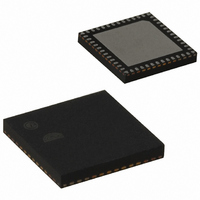
EM357-RTR Ember, EM357-RTR Datasheet - Page 153

EM357-RTR
Manufacturer Part Number
EM357-RTR
Description
IC RF TXRX ZIGBEE 192KB 48QFN
Manufacturer
Ember
Specifications of EM357-RTR
Frequency
2.4GHz
Data Rate - Maximum
250kbps
Modulation Or Protocol
802.15.4 Zigbee
Applications
General Purpose
Power - Output
5dBm
Sensitivity
-100dBm
Voltage - Supply
2.1 V ~ 3.6 V
Current - Receiving
26mA
Current - Transmitting
31mA
Data Interface
PCB, Surface Mount
Memory Size
192kB Flash, 12kB RAM
Antenna Connector
PCB, Surface Mount
Operating Temperature
-40°C ~ 85°C
Package / Case
48-QFN
Lead Free Status / RoHS Status
Lead free / RoHS Compliant
Other names
636-1011-2
Available stocks
Company
Part Number
Manufacturer
Quantity
Price
Company:
Part Number:
EM357-RTR
Manufacturer:
SILICON
Quantity:
3 000
Part Number:
EM357-RTR
Manufacturer:
SILICON
Quantity:
20 000
- Current page: 153 of 245
- Download datasheet (12Mb)
9.3.15 Timer Signal Descriptions
Signal
CK_INT
CK_PSC
ETR
ETRF
ETRP
ICy
ICyPS
ITR0
OCy
OCyREF
PCLK
TIy
TIyFPy
TIMxCy
TIMxCLK
TIMxMSK External Clock mask (if enabled) AND’ed with the other timer’s TIMxCLK signal.
TRGI
Internal/
External
Internal
Internal
Internal
Internal
Internal
External Input capture or clock: TIy after filtering and edge detection.
Internal
Internal
External Output compare: TIMxCy when used as an output. Same as OCyREF but includes possible
Internal
External Peripheral clock connects to CK_INT and used to clock input filtering. Its frequency is
Internal
Internal
Internal
External Clock input (if selected) to the external trigger signal (ETR).
Internal
Description
Internal clock source: connects to EM35x peripheral clock (PCLK) in internal clock mode.
Input to the clock prescaler.
External trigger input (used in external timer mode 2): a clock selected by
TIM_EXTRIGSEL in TIMx_OR.
External trigger: ETRP after filtering.
External trigger: ETR after polarity selection, edge detection and prescaling.
Input capture signal after filtering, edge detection and prescaling: input to the capture
register.
Internal trigger input: connected to the other timer’s output, TRGO.
polarity inversion.
Output compare reference: always active high, but may be inverted to produce OCy.
12 MHz if using the 24 MHz crystal oscillator and 6 MHz if using the 12 MHz RC oscillator.
Timer input: TIMxCy when used as a timer input.
Timer input after filtering and polarity selection.
Timer channel at a GPIO pin: can be a capture input (ICy) or a compare output (OCy).
Trigger input for slave mode controller.
Figure 9-36. Triggering Timer 1 and 2 with Timer 1 TI1 Input
Table 9-4. Timer Signal Descriptions
Final
9-29
EM351 / EM357
120-035X-000G
Related parts for EM357-RTR
Image
Part Number
Description
Manufacturer
Datasheet
Request
R

Part Number:
Description:
MODULE EM357 PA/LNA W/ANT TG
Manufacturer:
Ember
Datasheet:

Part Number:
Description:
MODULE EM357 NO PA/LNA W/ANT TG
Manufacturer:
Ember
Datasheet:

Part Number:
Description:
MODULE EM357 NO PA/LNA W/RF CONN
Manufacturer:
Ember
Datasheet:

Part Number:
Description:
MODULE EM357 PA/LNA W/RF CONN
Manufacturer:
Ember
Datasheet:

Part Number:
Description:
IC RF TXRX ZIGBEE 192KB 48QFN
Manufacturer:
Ember
Datasheet:

Part Number:
Description:
KIT DEV EMBER ZIGBEE W/PCWH
Manufacturer:
Custom Computer Services Inc (CCS)

Part Number:
Description:
PROGRAMMER USB FLASH EM250/260
Manufacturer:
Ember
Datasheet:

Part Number:
Description:
IC ZIGBEE SYSTEM-ON-CHIP 40-QFN
Manufacturer:
Ember
Datasheet:

Part Number:
Description:
IC ZIGBEE SYSTEM-ON-CHIP 48-QFN
Manufacturer:
Ember
Datasheet:

Part Number:
Description:
IC RF TXRX ZIGBEE 128KB 48QFN
Manufacturer:
Ember
Datasheet:

Part Number:
Description:
INSIGHT ADAPTER FOR EM2XX
Manufacturer:
Ember
Datasheet:

Part Number:
Description:
PROGRAMMER USB FLASH EM250/260
Manufacturer:
Ember
Datasheet:

Part Number:
Description:
IC ZIGBEE SYSTEM-ON-CHIP 40-QFN
Manufacturer:
Ember
Datasheet:

Part Number:
Description:
IC ZIGBEE SYSTEM-ON-CHIP 48-QFN
Manufacturer:
Ember
Datasheet:

Part Number:
Description:
IC RF TXRX ZIGBEE 128KB 48QFN
Manufacturer:
Ember
Datasheet:


