TR3000 RFM, TR3000 Datasheet
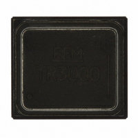
ASH TR 115.2 KBPS 433.92 MHZ

TR3000

Manufacturer Part Number
TR3000
Description
ASH TR 115.2 KBPS 433.92 MHZ
Manufacturer
RFM
Series
TRr
Datasheet

Specifications of TR3000

Frequency
433.92MHz
Data Rate - Maximum
115.2kbps
Modulation Or Protocol
ASK, OOK
Applications
General Data Transfer
Sensitivity
-101dBm
Voltage - Supply
2.2 V ~ 3.7 V
Current - Receiving
3.8mA
Current - Transmitting
7.5mA
Data Interface
PCB, Surface Mount
Antenna Connector
PCB, Surface Mount
Operating Temperature
-40°C ~ 85°C
Package / Case
SM-20L
Wireless Frequency
433.92 MHz
Operating Supply Voltage
2.5 V, 3.3 V
Maximum Operating Temperature
+ 85 C
Mounting Style
SMD/SMT
Maximum Data Rate
115.2 Kbps
Minimum Operating Temperature
- 40 C
Modulation
OOK/ASK
Lead Free Status / RoHS Status
Lead free by exemption / RoHS compliant by exemption
Power - Output
-
Memory Size
-
Lead Free Status / Rohs Status
Lead free / RoHS Compliant
Other names
583-1089-2

Available stocks

Company
Part Number
Manufacturer
Quantity
Price
Part Number:
TR3000
Manufacturer:
ON
Quantity:
40 000
Company:
Part Number:
TR3000
Quantity:
100
• Designed for Short-Range Wireless Data Communications
• Supports RF Data Transmission Rates Up to 115.2 kbps
• 3 V, Low Current Operation plus Sleep Mode
• Stable, Easy to Use, Low External Parts Count
• Complies with Directive 2002/95/EC (RoHS)
The TR3000 hybrid transceiver is ideal for short-range wireless data applications where robust operation,
small size, low power consumption and low cost are required. The TR3000 employs RFM’s amplifier-
sequenced hybrid (ASH) architecture to achieve this unique blend of character- istics. All critical RF functions
are contained in the hybrid, simplifying and speeding design-in. The receiver section of the TR3000 is
sensitive and stable. A wide dynamic range log detector, in combination with digital AGC and a compound
data slicer, provide robust performance in the presence of on-channel interference or noise. Two stages of
SAW filtering provide excellent receiver out-of-band rejection. The transmitter includes provisions for both on-
off keyed (OOK) and amplitude-shift keyed (ASK) modulation. The transmitter employs SAW filtering to
suppress output harmonics, facilitating compliance with ETSI I-ETS 300 220 and similar regulations.
Absolute Maximum Ratings
Electrical Characteristics
www.RFM.com
©2008 by RF Monolithics, Inc.
Rating
Power Supply and All Input/Output Pins
Non-Operating Case Temperature
Soldering Temperature (10 seconds / 5 cycles max.)
Characteristic
Operating Frequency
Modulation Types
OOK Data Rate
ASK Data Rate
Receiver Performance, High Sensitivity Mode
Receiver Performance, Low Current Mode
Receiver Out-of-Band Rejection, ±5% fo
Receiver Ultimate Rejection
Sensitivity, 2.4 kbps, 10-3 BER, AM Test Method
Sensitivity, 2.4 kbps, 10-3 BER, Pulse Test Method
Current, 2.4 kbps (R
Sensitivity, 19.2 kbps, 10-3 BER, AM Test Method
Sensitivity, 19.2 kbps, 10-3 BER, Pulse Test Method
Current, 19.2 kbps (R
Sensitivity, 115.2 kbps, 10-3 BER, AM Test Method
Sensitivity, 115.2 kbps, 10-3 BER, Pulse Test Method
Current, 115.2 kbps
Sensitivity, 2.4 kbps, 10-3 BER, AM Test Method
Sensitivity, 2.4 kbps, 10-3 BER, Pulse Test Method
Current, 2.4 kbps (R
E-mail: info@rfm.com
PR
PR
PR
= 330 K)
= 1100 K)
= 330 K)
Sym
R
R
±5%
f
ULT
o
-0.3 to +4.0
-50 to +100
Value
Notes
260
2
2
2
3
3
1
1
1
1
1
1
1
1
Minimum
433.72
Units
°C
°C
V
OOK & ASK
Typical
-109
-103
-105
-101
-104
100
3.0
-99
3.1
-95
3.8
-98
1.8
80
Transceiver
433.92 MHz
DEVELOPMENT KIT
TR3000
SM-20L Case
Hybrid
(Info
Maximum
Click
434.12
115.2
30
here)
TR3000 - 4/4/08
Page 1 of 12
Units
kbps
kbps
MHz
dBm
dBm
dBm
dBm
dBm
dBm
dBm
dBm
mA
mA
mA
mA
dB
dB

Related parts for TR3000

TR3000 Summary of contents

Page 1

... The TR3000 employs RFM’s amplifier- sequenced hybrid (ASH) architecture to achieve this unique blend of character- istics. All critical RF functions are contained in the hybrid, simplifying and speeding design-in. The receiver section of the TR3000 is sensitive and stable. A wide dynamic range log detector, in combination with digital AGC and a compound data slicer, provide robust performance in the presence of on-channel interference or noise ...

Page 2

... Vdc mV 10 P-P 85 ° Inches Min Nom Max .425 .430 .435 .375 .380 .385 .070 .075 .080 .120 .125 .130 .015 .020 .025 .035 .040 .045 .125 .130 .135 .070 .075 0.80 Page TR3000 - 4/4/08 ...

Page 3

... K ±5% K ±5% 4.7 µF tantalum 100 pF ±5% NPO 100 pF ±5% NPO Fair-Rite vendor 2506033017YO or equivalent ohm antenna 220 nH 50 ohm antenna R TH1 TH2 THLD 2 RREF 11 R REF GND2 10 LPF ADJ LPF Modulation Input Data Output Notes Page TR3000 - 4/4/08 ...

Page 4

... RFA1 is ON (up to 50%). SAW SAW Filter RFA1 Delay Line P1 Pulse Generator RF Data Pulse t PRI t PRC Figure 1 (RFA1 duty factor), where the 10 Detector & Data RFA2 Low-Pass Out Filter P2 Page TR3000 - 4/4/08 ...

Page 5

... CMPIN by separate series coupling capacitors. The AGC reset function is driven by the signal applied to CMPIN. BBOUT DS2 Ref Peak Detector C BBO dB Below PKDET 4 Peak Thld C PKD AGC DS1 Ref Thld Threshold Control THLD1 THLD2 R R TH1 TH2 R REF AND RXDATA 7 Page TR3000 - 4/4/08 ...

Page 6

... In the ASK mode TXA1 is biased ON continuously, and the output of TXA2 is modulated by the TXMOD input current. Minimum output power occurs in the ASK mode when the modulation driver sinks about 10 µA of current from the TXMOD pin. can be adjusted PW1 Page TR3000 - 4/4/08 ...

Page 7

... LPF = 1445/R LPF is in kilohms. LPF = 1750/f FGD LPF is in µ kHz, and R in kilohms. LPF LPF = C /19.1, where AGC = C /4167, PKA PKD kilohms PR is given kilohms set PW2 is in kilohms PW , where f is LPF LPF = 1.21*R , where LPF Page TR3000 - 4/4/08 ...

Page 8

... PKA and t in µs slaved to attack time PKA user selected mode user selected mode user selected mode user selected mode user selected mode in kHz user selected LPF in kilohms user selected LPF in pF user selected BBO Notes PKD Page TR3000 - 4/4/08 ...

Page 9

... MAX MAX Description , the capacitor value C AGH given above provides a hold-in time between t AGC , the capacitor value C is: BBO PKD and 1.5* t PKA For this case: MAX BBO AGC AGH with variations PKA for internal BBO and BBC Page TR3000 - 4/4/08 ...

Page 10

... PRC PRC TXM between this pin and LPF from 4.5 kHz to 1.8 MHz. LPF is in kHz to RREF. The threshold is TH1 can be adjusted between 0.1 and PRI is given by kilohms is in kilohms and 1.3* f LPF LPF TH2 from start-to-start PRC Page TR3000 - 4/4/08 ...

Page 11

... RF amplifier). The ON pulse width t PW2 - 18.6, where µs and kilohms PW1 PW1 PW SM-20L PCB Pad Layout .4600 0.000 Dimensions in inches with a resistor R to ground (the ON pulse PW1 PW is given by: PW .3825 .3575 .3175 .2775 .2375 .1975 .1575 .1175 .1025 .0775 Page TR3000 - 4/4/08 PW1 ...

Page 12

... RF Monolithics, Inc. RF Output Power 100 125 150 175 I in µA TXM TXM TXM 50 75 100 125 150 175 I in µA TXM Note: Specifications subject to change without notice. TXM 3 V 200 225 250 275 200 225 250 275 Page TR3000 - 4/4/08 ...

Related keywords