27980 Parallax Inc, 27980 Datasheet - Page 6
27980
Manufacturer Part Number
27980
Description
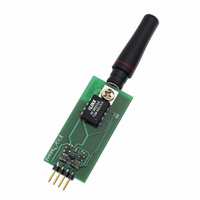
TRANSMITTER 433MHZ RF 4-SIP
Manufacturer
Parallax Inc
Datasheet
1.27981.pdf
(8 pages)
Specifications of 27980
Frequency
433.92MHz
Applications
Remote Sensors and Triggers
Data Rate - Maximum
19.2 kBaud
Current - Transmitting
10mA
Data Interface
PCB, Through Hole
Antenna Connector
On-Board, Whip
Voltage - Supply
5V
Package / Case
Module
Product
Microcontroller Accessories
Flash
512 KBytes
Timers
10 x 8 bit
Board Size
34.8 mm x 29.46 mm x 7.87 mm
Lead Free Status / RoHS Status
Contains lead / RoHS non-compliant
Features
-
Power - Output
-
Operating Temperature
-
Memory Size
-
Modulation Or Protocol
-
Lead Free Status / RoHS Status
Lead free / RoHS Compliant, Contains lead / RoHS non-compliant


GOTO Start
BASIC Stamp
The following BS2 programs will transmit (Tx) and receive (Rx) two word-sized counters (four bytes of
data). DATA line on the transmitter should be connected to I/O pin P8 of the BS2. The DATA line on the
receiver should be connected to I/O pin P7 of another BS2. The 5v and GND lines should be connected
to a +5 v source (Vdd) and ground (Vss) respectively (for both Tx and Rx). The BS2 on the receiving
end should remain connected to the computer to view the DEBUG statements.
TxCode_v_1.0.bs2
' TxCode_v_1.0.bs2
'{$STAMP BS2}
'{$PBASIC 2.5}
'
'Parallax 433.92 MHz RF Receiver (#27981) Sample Tx Code (BS2)
'Connect Pin 8 of the BS2 to the DATA line on the RF module
'Connect +5v to the 5v line, connect Ground to the GND line
'This code will transmit two word sized counters, byte at a time.
'
'Note the PULSOUT instruction: this helps the receiver sync with
'the transmitter, especially after lapses in communication
'This code transmits at 9600 baud, inverted.
x
y
DO
LOOP
RxCode_v_1.0.bs2
'RxCode_v_1.0.bs2
'{$STAMP BS2}
'{$PBASIC 2.5}
'Parallax 433.92 MHz RF Receiver (#27981) Sample Rx Code (BS2)
'Connect I/O Pin 7 of the BS2 to the DATA line on the RF module
'Connect +5v (Vdd) to the 5v line, connect Ground (Vss) to the GND line
'This code will look for an "!", then read in four bytes.
'The first two bytes will be the high and low bytes of a word variable (x),
'the second two bytes will be the high and low bytes of a second word variable (y).
'The values of x and y will be sent out to the DEBUG terminal.
'An optional LED (with proper current limiting resistor) may be connected to the
'BS2 I/O pin 0, this will blink when data is received.
'This code receives at 9600 baud, inverted.
x
y
DO
©Parallax, Inc. • 433.92 MHz RF Transmitter and Receiver (#27980, #27981) • v1.0
SERIN 1, N2400, ("!"), B3, B2, B5, B4
DEBUG x, y
PULSOUT 8, 1200
SEROUT
x = x + 1
y = y + 1
PAUSE 10
VAR
VAR
VAR
VAR
Word
Word
8, 16468, [ "!", x.HIGHBYTE, x.LOWBYTE, y.HIGHBYTE, y.LOWBYTE ]
Word
Word
®
2 Example Programs
'Sync pulse for the receiver
1/06
Page 6 of 8
Related parts for 27980
Image
Part Number
Description
Manufacturer
Datasheet
Request
R


Part Number:
Description:
Microcontroller Modules & Accessories DISCONTINUED BY PARALLAX
Manufacturer:
Parallax Inc

Part Number:
Description:
BOOK UNDERSTANDING SIGNALS
Manufacturer:
Parallax Inc
Datasheet:


Part Number:
Description:
COMPETITION RING FOR SUMOBOT
Manufacturer:
Parallax Inc
Datasheet:


Part Number:
Description:
TEXT INFRARED REMOTE FOR BOE-BOT
Manufacturer:
Parallax Inc
Datasheet:
Part Number:
Description:
BOARD EXPERIMENT+LCD NX-1000
Manufacturer:
Parallax Inc
Datasheet:

Part Number:
Description:
CONTROLLER 16SERVO MOTOR CONTROL
Manufacturer:
Parallax Inc
Datasheet:

Part Number:
Description:
BASIC STAMP LOGIC ANALYZER
Manufacturer:
Parallax Inc
Datasheet:

Part Number:
Description:
IC MCU 2K FLASH 50MHZ SO-18
Manufacturer:
Parallax Inc
Datasheet: