ATAB5278 Atmel, ATAB5278 Datasheet
ATAB5278
Specifications of ATAB5278


Related parts for ATAB5278


ATAB5278 Summary of contents
Page 1
LF Wake-up Demonstrator ATAK5278-82 1. General Description The LF wake-up demonstrator is provided to demonstrate the performance wake-up channel, mainly needed for battery-driven systems. Typical wake-up applica- tions can be found in vehicles for passive entry (PE) ...
Page 2
... Host PC running Windows • Power supply 8V to 15V Hardware Components The ATAB5278 transmitter interface is patched onto a microcontroller baseboard. The ATmega8515 microcontroller is programmed control the interface and to maintain com- munication with the host. Therefore, operation software has to be installed on the host via the enclosed CD-ROM ...
Page 3
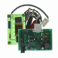
... Transmitter Board ATAB5278 The transmitter board is plugged into the baseboard via header pin connectors controlled by the ® AVR microcontroller on the baseboard through the SPI interface. In accordance with the features provided by the IC, the board is equipped with a choke for the boost converter needed to achieve a wide range of antenna current regulation independent of battery voltage and antenna impedance ...
Page 4
... Figure 3-2. Transmitter Board ATAB5278 ATAK5278-82 LF Wake-up Demonstrator 4 4894B–AUTO–06/06 ...
Page 5
Antenna Module The antenna module is matched by capacitor CANT (C1) to resonant frequency f = 125 kHz ±3 kHz. res Whereas the total antenna quality factor is adjusted by RANT (R1) to typical Q = 25. 3.2.1 Typical ...
Page 6
... Figure 3-4. Schematic of the Transmitter Board ATAB5278 X4_1 D1 VBATT 8V to 16V GND X4_2 C2 TP5 CANT Ext. Antenna Module X3_1 J2 TP1 CANT (C1) RANT (R1) J1 LANT X3_2 RANT T1 TP2 RSH ATAK5278-82 LF Wake-up Demonstrator VL1 VL3 OSCi OSCO VL2 4 VDS CBOOT ATA5278 6 CBOOST TP4 ...
Page 7
... Table 3-1. Parts List of ATA5278 Antenna Interface, ATAB5278 Part No. Designation U1 Transmitter IC T1 MOS transistor D1 Diode D2 Diode D3 Suppressor diode LD1 LED R1 Resistor R2 Resistor RSH Resistor RINT Resistor RANT Resistor C1 Capacitor C2 Capacitor C3 Capacitor C4/1 Capacitor C4/2 Capacitor C5 Capacitor C6 Capacitor CINT Capacitor CBOOTNT Capacitor ...
Page 8
Receiver Board ATAB5282 In addition to the three-channel LF receiver IC, the board is equipped with a 3D antenna (Pre- dan). The antenna has a sensitivity in all directions of approximately 100 mV/Am. Reaching a bandwidth of 4 kbits/s, ...
Page 9
... 100 k 100 100 10 k 3V/220 mAh 2 3 pole Type Manufacturer ATA5282 Atmel BC857 TLMT 3100 Vishay 3DC1515S-0477X Predan P-749 002 SMD ceramic e.g., Vishay SMD ceramic e.g., Vishay SMD ceramic e.g., Vishay Tantal e.g., Vishay Tantal e.g., Vishay ...
Page 10
Receiver Board ATAB5283 (Optional Offer): The board, mainly preferred for TPMS applications, is equipped with antenna (Predan). Received data are indicated by an additional LED display. Once the IC is woken up, it remains in active ...
Page 11
... SMD Ceramic 10 µF/10V Optional 100 k 100 47 k 100 k 100 10 k 100 k MPD BA2032SM 3V/220 mAh 2 3 pole Type Manufacturer ATA5283 Atmel BC857 BC847 TLMT 3100 Vishay Predan e.g., Vishay e.g., Vishay e.g., Vishay Tantal e.g., Vishay MPD Inc. CR2032 ITT-Cannon 11 ...
Page 12
... The host communicates via software with the AVR microcontroller ATmega8515 located on the baseboard. Further, the microcontroller, programmed in C, also maintains the dialog with the ATAB5278 transmitter IC via its SPI interface. When executing the program file ATA5278.exe, the setup menu as seen in The menu enables setting and checking of configuration states as well creating, saving and reloading the data protocol to be sent ...
Page 13
Configuration Register 1 Enables to set and to check the configuration of the transmitter with regard to the matter of mod- ulation (ASK or PSK) and antenna current level. By pull down menu the antenna current is selectable from ...
Page 14
... Using an English language system: – Using a German language system: • When the software program Atab5278.exe (located in the installation folder) is executed, the host operating menu appears as seen in • Insert the battery into the battery slot of the ATAB5282 (ATAB5283) receiver board and place the board inside the antenna field • ...
Page 15
... When the Single button is clicked, the loaded protocol data is sent once by the transmitter. Each protocol cycle received is indicated by LED on the receiver board ATAB5282. Using the default ATAB5278 transmitter antenna current value (Iant = 1A receiver should be able to detect the protocol at a distance of at least 2 meters along the antenna axis • ...
Page 16
... Signal Transmission Tx-Rx Measurements Figure 6-3. Signal Transmission ATAB5278 Transmitter to ATA5282 Receiver Figure 6-4. Signal Transmission ATAB5278 Transmitter to ATA5283 Receiver ATAK5278-82 LF Wake-up Demonstrator 16 4894B–AUTO–06/06 ...
Page 17
... QSC Feature Measurement at ATAB5278 Board Data transmission without QSC function can be performed by shorting QSC transistor T1 (con- nect TP2 with x3_2). Due to the antenna’s Q factor, the current and voltage signals do not reach final pulse level of protocol data nal slope and the smaller the reachable signal data rate. ...
Page 18
Figure 6-6. Sent Data With QSC 6.4 Current Setting The antenna current setting can be selected from 16 levels via drop-down menu In default mode the maximum current is set to typically 1000 mA. Related antenna current mea- surements with ...
Page 19
PSK Modulation Special applications may need to transmit data by PSK modulation of the 125 kHz carrier fre- quency. Even though an appropriate receiver is not available, the modulation can be done by the ATA5278, as shown in Figure ...
Page 20
Diagnosis Functions The IC protects itself from destruction if a fault occurs. For demonstration, the antenna diagnosis information can be checked and readout using the Status Register menu. 6.6.1 Antenna Short Circuit During Protocol Sent • Short TP5 to ...
Page 21
... Disclaimer: The information in this document is provided in connection with Atmel products. No license, express or implied, by estoppel or otherwise, to any intellectual property right is granted by this document or in connection with the sale of Atmel products. EXCEPT AS SET FORTH IN ATMEL’S TERMS AND CONDI- TIONS OF SALE LOCATED ON ATMEL’S WEB SITE, ATMEL ASSUMES NO LIABILITY WHATSOEVER AND DISCLAIMS ANY EXPRESS, IMPLIED OR STATUTORY WARRANTY RELATING TO ITS PRODUCTS INCLUDING, BUT NOT LIMITED TO, THE IMPLIED WARRANTY OF MERCHANTABILITY, FITNESS FOR A PARTICULAR PURPOSE, OR NON-INFRINGEMENT ...