STARTKIT-M24LR-A STMicroelectronics, STARTKIT-M24LR-A Datasheet
STARTKIT-M24LR-A
Specifications of STARTKIT-M24LR-A
Available stocks


Related parts for STARTKIT-M24LR-A


STARTKIT-M24LR-A Summary of contents
Page 1
Introduction The purpose of this user manual is to teach how to use the M24LR64-R tool kit with the M24LRxx_Application_Software. It describes the M24LRxx_Application_Software interface and its menus, and shows how to send commands to M24LR64-R tags. January 2010 ...
Page 2
Contents Contents 1 Introduction . . . . . . . . . . . . . . . . . . . . . . . . . . . . . . . . . . . . ...
Page 3
UM0853 4.1 Check communication . . . . . . . . . . . . . . . . . . . . . . . . . . . . . . . . . . . . ...
Page 4
List of figures List of figures Figure 1. RF reader (ISO 15693, RF 13.56 MHz ...
Page 5
UM0853 Figure 49. Warning before locking the DSFID field . . . . . . . . . . . . . . . . . . . . . . . . . . . . . . . ...
Page 6
List of figures Figure 101. RF upload process failed . . . . . . . . . . . . . . . . . . . . . . . . . . . . . . . ...
Page 7
UM0853 2 Tool kit descriptions 2.1 Development kit Ordering information: DEVKIT-M24LR-A The development kit contains: ● a middle-range RF reader (ISO 15693, RF 13.56 MHz) interfaced via the USB bus and an external power supply to have a greater read ...
Page 8
Tool kit descriptions Figure 3. Serial EEPROM USB reader Figure 4. I²C bus cable Figure 5. ANT1-M24LR-A reference antenna Figure 6. ANT2-M24LR-A reference antenna 8/49 Doc ID 16609 Rev 1 UM0853 ...
Page 9
UM0853 Figure 7. M24LR64-R in SO8 package 2.2 M24LR64-R demonstration kit Ordering information: DEMOKIT-M24LR-A The demonstration kit contains: ● a middle-range RF reader (ISO 15693, RF 13.56 MHz) interfaced via the USB bus, shown in Figure 8 ● an M24LR64-R’s ...
Page 10
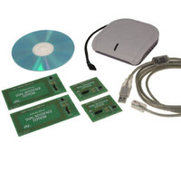
... Tool kit descriptions Figure 10. STM32-PRIMER2 1. Not included in the kit ordered separately. Starter kit 2.3 Ordering information: STARTKIT-M24LR-A The starter kit contains: ● a short-range RF reader (ISO 15693, RF 13.56 MHz), interfaced via the USB bus (including the external I²C bus cable + connector) illustrated in ● ...
Page 11
UM0853 Figure 12. ANT1-M24LR-A reference antenna Figure 13. ANT2-M24LR-A reference antenna Figure 14. M24LR64-R in SO8 package Doc ID 16609 Rev 1 Tool kit descriptions 11/49 ...
Page 12
How to control the RF and I²C channels from your screen 3 How to control the RF and I²C channels from your screen 3.1 Starting M24LRxx_Application_Software Before starting, you must have: ● previously installed all the drivers. For how to ...
Page 13
UM0853 Once the kit has been selected, the software checks that the selected readers are well connected. A progress bar appears during the check as shown in Figure 16. Connection check by the software If a problem occurs, a window ...
Page 14
How to control the RF and I²C channels from your screen Figure 17. Main menu window You can use the menu at the top of the window to select several applications: Reader Application menu Select show Reader application M24LR64-R. Figure ...
Page 15
UM0853 3.1.3 Image Transfer Application menu Figure 19 shows the Image Transfer Application menu. Select show Image Transfer application to upload or download a picture to or from the M24LR64 I²C. Figure 19. show Image Transfer application ...
Page 16
How to control the RF and I²C channels from your screen 3.1.5 Tools menu Figure 21 shows the Tools menu. Select stop animation to stop the animation in the reader application interface. Figure 21. Tools menu 3.1.6 Help menu Figure ...
Page 17
UM0853 The Show I2C Commands button is used to switch from the RF user interface to the I²C user interface. Figure 23. RF user interface 3.2.1 Inventory command The Inventory button launches an Inventory command and thus detects the tags ...
Page 18
How to control the RF and I²C channels from your screen Figure 25. Three tags detected You can select a tag in the list of detected UIDs by clicking on the desired UID in the list as shown in Figure ...
Page 19
UM0853 The RF TAG ANSWER report button shows the RF answer from the tag, detected by the RF reader. Figure 29 shows an example of a reader’s RF request and the corresponding answer from the tag. Figure 29. RF request ...
Page 20
How to control the RF and I²C channels from your screen Select mode Selecting the Select mode sets bit 5 and clears bit 6 in the Request_flags of the RF request (bit and bit 6 = 0). ...
Page 21
UM0853 By pressing the Read button, you launch RF requests to read the contents of the M24LR64- R EEPROM from the block address specified in the from field to the block address specified in the to field. The result of ...
Page 22
How to control the RF and I²C channels from your screen Figure 36. Result of the read operation - Sector 3Fh Use the arrows on the keyboard to change the sector or block to be read. From 0000 to 0000 ...
Page 23
UM0853 Example: in Figure 38 49 (49h Hex) is the first piece of data read in block number 0002 (sector 0) 46 (46h Hex) is the second piece of data read in block number 0002 (sector 0) 00 (00h Hex) ...
Page 24
How to control the RF and I²C channels from your screen Figure 42. Security status byte for sector 07 Figure 43 shows the security status bytes for the blocks located at addresses 00FAh to 0109h (sector 07 & sector 08). ...
Page 25
UM0853 3.2.9 Write DSFID command The Write DSFID button launches a Write DSFID command. The data in the dedicated field next to the Write DSFID button are written to the DSFID register. Figure 45. Write DSFID command 3.2.10 Lock AFI ...
Page 26
How to control the RF and I²C channels from your screen Figure 49. Warning before locking the DSFID field 3.2.12 RF password management The user interface displays a warning concerning password changes: you should be very careful when you change ...
Page 27
UM0853 Figure 51. Present-sector Password command The result of the Present-sector Password command appears in the RF answer field. Figure 52 shows a successful command, and occurred. Figure 52. Present-sector Password command successful Figure 53. Present-sector Password command error Write-sector ...
Page 28
How to control the RF and I²C channels from your screen Figure 56. Write-sector Password command successful Write Password HS Figure 57. Write-sector Password command error Lock-sector Password command The Lock sector button issues a Lock-sector Password command with the ...
Page 29
UM0853 Figure 62. I2C User Interface window 3.3.1 I2C READ commands The Read button issues read commands to the M24LR64-R connected to the I2C reader so, select the I2C READ area, and then press on the Read button. ...
Page 30
How to control the RF and I²C channels from your screen Figure 64. Result of a Read operation to the memory array Figure 64 illustrates the result of the Read operation to the memory array. The first column shows which ...
Page 31
UM0853 Figure 66. Result of the read sector security status operation Reading the I2C_Write_Lock bit area To read the 2C_Write_Lock bit area (I2C sector security), select I2C write lock bits (system) and press the Read button. Figure 67 shows how ...
Page 32
How to control the RF and I²C channels from your screen Figure 69. Reading the system parameter sector Figure 70. Result of the read system parameter sector operation Please, refers to the M24LR64-R dataheet for the system parameters. 3.3.2 I2C ...
Page 33
UM0853 In this example, a write operation is issued to write the data < > to EEPROM memory addressses 0000 to 003F by I2C communication. Note that in the I2C answer, you are notified of whether ...
Page 34
How to control the RF and I²C channels from your screen Figure 76. Writing A1 to the memory array Writing to the sector security status area To write to the sector security status area, select Sector Security Status (system) and ...
Page 35
UM0853 Figure 78. Result of the write to sector security status area operation Writing to the I2C_Write_Lock bit area To write to the I2C_Write_Lock bit area, select I2C write lock bits (system) and fill the address range to be written, ...
Page 36
How to control the RF and I²C channels from your screen 3.3.3 I2C PASSWORD commands In the I2C PASSWORD area of the I2C User Interface window (see Present Password to be able to send an I2C Present Password command. The ...
Page 37
UM0853 Figure 83. Warning Note that in the I2C answer, you are notified of whether the write cycle succeeded or failed (see Figure 84 and Figure 84. Write Password cycle successful Figure 85. Write Password cycle failed (no cycle detected) ...
Page 38
Data transfer management (picture demo) 4 Data transfer management (picture demo) Select show Image Transfer Application from the main menu of the M24LRxx_Application_Software application. Figure 86. Show Image Transfer Application window The show Demo application allows you to play with ...
Page 39
UM0853 4.1.1 Check communication by RF After clicking on check RF communication, the button changes to running as shown in Figure 88. If the circle next to the running button is green, the communication by RF between the M24LR64-R and ...
Page 40
Data transfer management (picture demo) 4.2 Writing a picture to your M24LR64-R In the show Demo application window the WRITE PICTURE TO M24LR64 area (see Figure 92) , and choose the picture you would like to upload into ...
Page 41
UM0853 Figure 95. Uploading the picture by I2C To upload the picture by RF, click shown below. Figure 96. Selecting RF to upload the picture You then have to click on the Upload by RF button to ...
Page 42
Data transfer management (picture demo) Figure 101. RF upload process failed 4.3 Read/display the M24LR64-R’s contents In the show Demo application window, the READ M24LR64 CONTENT area allows you to display the contents of the memory on your computer screen ...
Page 43
UM0853 Figure 105. Selecting RF to download the picture You then have to click on the Upload by RF button to launch the upload process (see Figure 106). Figure 106. Downloading the picture by RF The application reads the contents ...
Page 44
Demo application for use with DEMOKIT-M24LR-A 5 Demo application for use with DEMOKIT-M24LR-A The demo application window, shown in M24LR-A kit. All the pictures are in the bitmap format to be compliant with the STM32- PRIMER2 firmware and LCD screen ...
Page 45
UM0853 5.2 Uploading a picture to your DEMOKIT-M24LR Use the frame shown below to upload a picture by RF. Figure 114. Upload frame Click on a picture to upload the picture in bmp format to the M24LR64-R by ...
Page 46
Demo application for use with DEMOKIT-M24LR-A Figure 116. HELLO WORLD picture downloaded Figure 117. ST logo downloaded 5.4 Check communication status You can use the CHECK COMMUNICATION area to verify whether the data were written or read successfully or not. ...
Page 47
UM0853 5.5 Using your STM32-PRIMER2 to read the contents of the reference antenna by I2C If the picture was uploaded described above, you will be able to display it on the LCD screen of your STM32-PRIMER2. Please ...
Page 48
Revision history 6 Revision history Table 1. Document revision history Date 28-Jan-2010 48/50 Revision 1 Initial release. Doc ID 16609 Rev 1 UM0853 Changes ...
Page 49
... UM0853 Information in this document is provided solely in connection with ST products. STMicroelectronics NV and its subsidiaries (“ST”) reserve the right to make changes, corrections, modifications or improvements, to this document, and the products and services described herein at any time, without notice. All ST products are sold pursuant to ST’s terms and conditions of sale. ...