TMEB8704 Atmel, TMEB8704 Datasheet
TMEB8704
Specifications of TMEB8704


Related parts for TMEB8704


TMEB8704 Summary of contents
Page 1
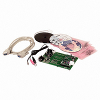
... RFID Application Kit TMEB8704 1. Introduction The RFID application kit TMEB8704 is designed to demonstrate the key features of Atmel’s various RFID products. The included software version IDS 5 supports the fol- lowing products: • U2270B on the reader side • TK5530/e5530 on the transponder side • TK5551/e5551 on the transponder side • ...
Page 2
... Hardware Settings and Connector Positions In RFID applications, the main board with the microcontroller is operated in a fixed configuration; no settings are necessary. Check jumper J3 on the antenna interface to verify that it is has the default setting (see Figure 2-1. TMEB8704 Application Note 2 Figure 2-1 and Figure 2-2 on page ...
Page 3
... RFID application kit on the cover. Insert the CD-ROM into the CD-ROM drive and execute setup.exe. The program (including all libraries needed) will be installed automatically. Note: 4781A–RFID–10/05 Application Board Topview It is necessary to have write permission for the system. TMEB8704 Application Note 3 ...
Page 4
... The board is equipped with two stages of high-voltage transistor switches to tune the resonator by switched capacitors. This increases the reliability and operating distance. The frequency tuning can be selected using jumper J3 (see TMEB8704 Application Note 4 Figure 2-2 on page Figure 2-2 on page 3) can be changed ...
Page 5
... The currently selected frequency stage is indicated in binary mode on the application board by the red LEDs Tune 1 and Tune 2 (see 3.3.2 RF Field Control The status of the RF field controlled by the microcontroller is indicated by the yellow LED RF On. 4781A–RFID–10/05 TMEB8704 Application Note Tuning Mode Selection Tuning Mode Disabled Enabled Figure 2-2 on page Jumper J3 Position 1 – ...
Page 6
... Circuit Diagram of the Antenna Interface Figure 3-1. Circuit Diagram of the Antenna Interface TMEB8704 Application Note 6 4781A–RFID–10/05 ...
Page 7
... LD1 LD2 LD3 LD4 Transistors Resistors R10 R11 R12 R13 R14 R15 R16 R17 R18 R19 R20 R21 R22 4781A–RFID–10/05 TMEB8704 Application Note = U2270B = LM7808 = BAS21 = BAS21 = BAS21 = BAS21 = BAS21 = BAS21 = BAS21 = BZX84C = TLMC3100 (green) = TLMT3100 (red) = TLMT3100 (red) = ...
Page 8
... Gold-pin block for jumper ( pole) • 2 gold-pin block pole (used for header connector to the main board) The antenna coil included in the IDIC application kit measures the following parameters related to 125 kHz: Inductance Coil diameter Winding number Wire diameter TMEB8704 Application Note 8 = 2.2 nF (5%) = 150 pF = 100 pF ...
Page 9
... Click on Configure Transponder (this function programs the configuration block, Block 0, of the TK5552) • Choose the Write tab to program Blocks the transponder memory • Select Program Transponder • To read out the transponder, click the Read button in the Read tab to show the transponder code 4781A–RFID–10/05 TMEB8704 Application Note 9 ...
Page 10
... To start the encryption process, choose the Authentication tab to program Blocks the transponder memory • Click Program Transponder • Click Start Authentication for encryption process 4.1.6 Exit the Program • Choose Exit from the main menu to quit the program TMEB8704 Application Note 10 4781A–RFID–10/05 ...
Page 11
... Setup When the submenu Transponder in the Setup menu is selected, the different types of Atmel’s transponders can be seen (see the user interface will be adjusted. 4781A–RFID–10/05 TMEB8704 Application Note RFID Application Kit 5 Software Figure 5-2 on page 12). Depending on the transponder chosen, 11 ...
Page 12
... In autotuning mode, the software switches between the four frequencies until the transponder can be read out. The currently selected frequency stage is indicated, binary encoded, on the application board by the Tune 1/Tune 2 LEDs (see TMEB8704 Application Note 12 Transponder Menu Figure 5-3) ...
Page 13
... The submenu About in the main menu Info shows the program version and creation date. 4781A–RFID–10/05 Binary Tuning LED Code Tune 2 Tune 5-5). The status is indicated by the yellow RF On LED on the application board. RF RF-Field Menu Application Menu TMEB8704 Application Note Frequency High Semi-high Semi-low (default) Low 13 ...
Page 14
... In a real-time analysis, the incoming data stream is decoded to binary values and sent to the PC. Clicking on the button Default restores the default setting. Click the Cancel button to leave the TK5530 user interface. TMEB8704 Application Note 14 TK5530 Read Tab For details, please refer to the e5530 datasheet. ...
Page 15
... TK5551 Read Tab The U2270B is not able to read all displayed bit rates and coding types. If invalid settings are selected, a warning message will be displayed. For details, please refer to the e5551 datasheet. TMEB8704 Application Note 15 ...
Page 16
... Once set, the informa- tion cannot be overwritten. (Please use this feature with care.) Default restores the default setting. To leave the TK5551 user interface, click Cancel. TMEB8704 Application Note 16 TK5551 Write Tab ...
Page 17
... Type the password for a specific transponder into the Password text field 2. Click on the AOR wake-up button to activate the specific transponder 3. Read out the transponder by clicking Read 4. To stop the read function, click Stop Transponder-Modulation 5. Repeat steps for the next transponder, using the appropriate password 4781A–RFID–10/05 TMEB8704 Application Note 17 ...
Page 18
... To read out the transponder, use the Read button. The decoding principle, in simple terms send the chosen Configuration and Read Timing to the microcontroller on the RFID application TMEB8704 Application Note 18 The U2270B is not able to read all bit rates and coding types displayed. If invalid settings have been selected, a warning message will be displayed ...
Page 19
... TK5561 Read/Write/Crypto Transponder When the transponder TK5561 is selected, the Read tab of the TK5561 user interface is shown. This sheet enables to set the following parameters in the Configuration Setup (on the left side): • Bit rate: Rf/32 and Rf/64 4781A–RFID–10/05 TMEB8704 Application Note 19 ...
Page 20
... POR.) To leave the TK5561 user interface, click on the Cancel button. Clicking the Direct Access... button makes blockwise reading possible. Figure 5-12. TK5561 Read Tab TMEB8704 Application Note 20 The U2270B is not able to read all bit rates and coding types displayed transponder is config- ured in an invalid mode, a warning message will be displayed ...
Page 21
... Figure 5-13. TK5561 Write Tab 4781A–RFID–10/05 TMEB8704 Application Note 21 ...
Page 22
... Write column. With the Start Authentica- tion button, the challenge is sent to the transponder and the authentication procedure is started. Clicking the button Default restores the default setting. To leave the TK5561 user interface, click on the Cancel button. TMEB8704 Application Note 22 4781A–RFID–10/05 ...
Page 23
... PC. Clicking on the button Default restores the default setting. Clicking the Stop Transpon- der-Modulation button sends the stop command to the transponder (this halts modulation until POR). To leave the U9280M user interface, click on the Cancel button. 4781A–RFID–10/05 TMEB8704 Application Note 23 ...
Page 24
... Figure 5-15. U9280M Read Tab Figure 5-16. U9280M Write Tab TMEB8704 Application Note 24 4781A–RFID–10/05 ...
Page 25
... If both responses are equal, the AUT64 result displays OKAY; if unequal, the AUT64 result displays Error AUT64. The user can change the input parameters and key data of the encryption algorithm. Note: 4781A–RFID–10/05 Remark: Data value in block 6 is restricted: The 3 LSB of each nibble must be different. TMEB8704 Application Note 25 ...
Page 26
... Figure 5-18. Message Box AUT64 Result TMEB8704 Application Note 26 4781A–RFID–10/05 ...
Page 27
... Disclaimer: The information in this document is provided in connection with Atmel products. No license, express or implied, by estoppel or otherwise, to any intellectual property right is granted by this document or in connection with the sale of Atmel products. EXCEPT AS SET FORTH IN ATMEL’S TERMS AND CONDI- TIONS OF SALE LOCATED ON ATMEL’S WEB SITE, ATMEL ASSUMES NO LIABILITY WHATSOEVER AND DISCLAIMS ANY EXPRESS, IMPLIED OR STATUTORY WARRANTY RELATING TO ITS PRODUCTS INCLUDING, BUT NOT LIMITED TO, THE IMPLIED WARRANTY OF MERCHANTABILITY, FITNESS FOR A PARTICULAR PURPOSE, OR NON-INFRINGEMENT ...