STEVAL-TDR017V1 STMicroelectronics, STEVAL-TDR017V1 Datasheet
STEVAL-TDR017V1
Specifications of STEVAL-TDR017V1


Related parts for STEVAL-TDR017V1


STEVAL-TDR017V1 Summary of contents
Page 1
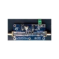
Features ■ Excellent thermal stability ■ Common source configuration ■ Broadband performances P with 15 dB gain @ 870 MHz ■ Plastic package ■ ESD protection ■ Supplied in tape and reel ■ In compliance with the 2002/95/EC european directive ...
Page 2
Contents Contents 1 Electrical data . . . . . . . . . . . . . . . . . . . . . . . . . . . . . . . . . . . ...
Page 3
PD84001 1 Electrical data 1.1 Maximum ratings Table 2. Absolute maximum ratings (T Symbol V (BR)DSS DISS STG 1.2 Thermal data Table 3. Thermal data Symbol R thJC CASE Parameter Drain-source voltage ...
Page 4
Electrical characteristics 2 Electrical characteristics 2.1 Static Table 4. Static (T Symbol DSS GSS GS( DS(ON) GS ...
Page 5
PD84001 3 Impedance Figure 2. Current conventions Table 8. Impedance data Freq. (MHz) 920 900 880 860 840 820 800 Z (Ω) GS 4.0 + j4.3 3.6 + j4.3 3.3 + j4.1 3.1 + j3.7 2.9 + j3.4 2.8 + ...
Page 6
Typical performance 4 Typical performance Figure 6/18 Figure 4. DC output characteristics PD84001 ...
Page 7
PD84001 Figure RSS DS 3.2 3.0 2.8 2.6 2.4 2.2 2.0 1.8 1.6 1.4 1.2 1.0 0.8 0.6 0.4 0.2 0 Vds (V) CRSS Figure 7. C ...
Page 8
Typical performance Figure 8. Gain vs output power and frequency Pout (dBm) 840 MHz 870 MHz Figure 10. Efficiency vs output power and frequency ...
Page 9
PD84001 Figure 12. Input return loss vs frequency -10 810 820 830 840 850 860 870 880 890 900 910 920 Freq (MHz) Figure 14. Efficiency vs output power and ...
Page 10
Typical performance Figure 16. Gain and efficiency vs pin Gain-70mA Eff-70mA 10/18 y Freq = 520 MHz Vdd = 7. Pin (dBm) Gain-200mA Gain-50mA ...
Page 11
PD84001 5 Test circuit Figure 17. Test circuit schematic / 840-900 MHz Test circuit 11/18 ...
Page 12
Package mechanical data 6 Package mechanical data In order to meet environmental requirements, ST offers these devices in ECOPACK® packages. These packages have a lead-free second level interconnect . The category of second level interconnect is marked on the package ...
Page 13
PD84001 Table 9. SOT-89 mechanical data Dim Figure 18. Package dimensions mm. Min Typ Max 1.4 1.6 0.44 0.56 0.36 0.48 0.35 0.44 0.35 0.44 4.4 4.6 1.62 ...
Page 14
Package mechanical data 6.1 Thermal pad and via design Thernal vias are required in the PCB layout to effectively conduct heat away from the package. The via pattern has been designed to address thermal, power dissipation and electrical requirements of ...
Page 15
PD84001 6.2 Soldering profile Figure 20 shows the recommeded solder for devices that have Pb-free terminal plating and where a Pb-free solder is used. Figure 20. Recommended solder profile Figure 21 shows the recommeded solder for devices with Pb-free terminal ...
Page 16
Package mechanical data Figure 22. Reel information 16/18 PD84001 ...
Page 17
PD84001 7 Revision history Table 10. Document revision history Date 06-Dec-2006 16-May-2007 05-Jun-2007 25-Aug-2008 Revision 1 Initial release 2 Marking updated 3 Part number update 4 Updated Table 4 on page 4 Revision history Changes 17/18 ...
Page 18
... Information in this document is provided solely in connection with ST products. STMicroelectronics NV and its subsidiaries (“ST”) reserve the right to make changes, corrections, modifications or improvements, to this document, and the products and services described herein at any time, without notice. All ST products are sold pursuant to ST’s terms and conditions of sale. ...