MEK350-02DA IXYS, MEK350-02DA Datasheet
MEK350-02DA
Manufacturer Part Number
MEK350-02DA
Description
DIODE FRED 200V 356A 150NS
Manufacturer
IXYS
Datasheet
1.MEK350-02DA.pdf
(2 pages)
Specifications of MEK350-02DA
Voltage - Forward (vf) (max) @ If
1.07V @ 260A
Current - Reverse Leakage @ Vr
3mA @ 200V
Current - Average Rectified (io) (per Diode)
356A
Voltage - Dc Reverse (vr) (max)
200V
Reverse Recovery Time (trr)
200ns
Diode Type
Standard
Speed
Fast Recovery =< 500ns, > 200mA (Io)
Diode Configuration
1 Pair Common Cathode
Mounting Type
Chassis Mount
Package / Case
Y4-M6
Vrrm, (v)
200
Ifavm, D = 0.5, Total, (a)
356
@ Tc, (°c)
75
Ifrms, (a)
503
Ifsm, 10 Ms, Tvj = 45°c, (a)
2400
Vf, Max, Tvj = 150°c, (v)
0.92
@ If, (a)
260
Trr, Typ, Tvj =25°c, (ns)
150
Irm , Max, Tvj = 100°c, (a)
15
@ -di/dt, (a/µs)
200
Rthjc, Max, (k/w)
0.143
Ptot, Max, (w)
875
Package Style
Y4-M6
Lead Free Status / RoHS Status
Lead free / RoHS Compliant
Other names
Q1147009
Available stocks
Company
Part Number
Manufacturer
Quantity
Price
Company:

Part Number:
MEK350-02DA
Manufacturer:
IXYS
Quantity:
28
Company:
Part Number:
MEK350-02DA
Manufacturer:
SMD
Quantity:
300
Part Number:
MEK350-02DA
Quantity:
60


© 2000 IXYS All rights reserved
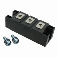
Fast Recovery
Epitaxial Diode
(FRED) Module
Symbol
I
I
I
I
I
T
T
T
P
V
M
d
d
a
Weight
Symbol
I
V
V
r
R
R
t
I
Data according to IEC 60747
IXYS reserves the right to change limits, test conditions and dimensions
FRMS
FAVM
FRM
FSM
2
R
rr
RM
T
V
200
t
VJ
stg
Smax
S
A
tot
ISOL
F
T0
thJH
thJC
d
RSM
V
I
FAVM
ÿÿ
rating includes reverse blocking losses at T
-di/dt =
V
200
RRM
V
T
T
t
T
T
T
T
T
50/60 Hz, RMS t = 1 min
I
Mounting torque (M6)
Terminal connection torque (M6)
Creeping distance on surface
Strike distance through air
Maximum allowable acceleration
T
T
T
I
I
For power-loss calculations only
DC current
DC current
I
V
Test Conditions
Test Conditions
P
ISOL
F
F
F
C
C
VJ
VJ
VJ
VJ
C
VJ
VJ
VJ
R
< 10 ms; rep. rating, pulse width limited by T
=
=
=
=
= 25°C
=
=
= 45°C;
= 150°C; t = 10 ms (50 Hz), sine
= 45°C;
= 150°C; t = 10 ms (50 Hz), sine
= 25°C
= 25°C
= 125°C
£ 1 mA
150
260
300
100
200
75
75
°C
°C; rectangular, d = 0.5
A;
A;
V
A
A/ms
Type
MEK 350-02DA
t = 10 ms (50 Hz), sine
t = 8.3 ms (60 Hz), sine
t = 8.3 ms (60 Hz), sine
t = 10 ms (50 Hz), sine
t = 8.3 ms (60 Hz), sine
t = 8.3 ms (60 Hz), sine
V
V
V
T
T
T
T
VJ
VJ
VJ
VJ
R
R
R
t = 1 s
= V
= 0.8 • V
= 0.8 • V
= 125°C
= 25°C
= 125°C
= 25°C
RRM
T
T
T
VJ
VJ
VJ
= 100°C
= 25°C
= 100°C
RRM
RRM
VJM
, V
R
= 0.6 V
RRM
Characteristic Values (per diode)
, duty cycle d = 0.5
MEK 350-02 DA
VJM
150
typ.
2.25-2.75/20-25
4.50-5.50/40-48
1
Maximum Ratings
-40...+150
-40...+125
max.
28800
29300
23300
23800
0.228
0.143
2400
2640
2160
2380
3000
3600
1800
12.7
0.98
1.07
0.53
1.29
0.80
0.92
503
356
110
875
150
200
9.6
50
80
15
2
3
2
9
Nm/lb.in.
Nm/lb.in.
m/s
K/W
K/W
mm
mm
mW
A
A
A
A
mA
mA
mA
V~
V~
°C
°C
°C
ns
W
A
A
A
A
A
A
A
g
V
V
V
V
V
A
A
2
2
2
2
s
s
s
s
3
2
V
I
t
Features
Applications
Advantages
Dimensions in mm (1 mm = 0.0394")
FAVM
rr
International standard package
with DCB ceramic base plate
Planar passivated chips
Short recovery time
Low switching losses
Soft recovery behaviour
Isolation voltage 3600 V~
UL registered E 72873
Antiparallel diode for high frequency
switching devices
Free wheeling diode in converters
and motor control circuits
Inductive heating and melting
Uninterruptible power supplies (UPS)
Ultrasonic cleaners and welders
High reliability circuit operation
Low voltage peaks for reduced
protection circuits
Low noise switching
Low losses
RRM
= 200 V
= 356 A
= 150 ns
1
2
3
1 - 2
Related parts for MEK350-02DA
Image
Part Number
Description
Manufacturer
Datasheet
Request
R


Part Number:
Description:
HiPerFET Power MOSFETs
Manufacturer:
IXYS Corporation
Datasheet:
Part Number:
Description:
J-K-Type Flip-Flop
Manufacturer:
IXYS Corporation
Datasheet:
Part Number:
Description:
HiPerRF Power MOSFETs
Manufacturer:
IXYS Corporation
Datasheet:
Part Number:
Description:
Rectifier Module for Three Phase Power Factor Correction
Manufacturer:
IXYS Corporation
Datasheet:
Part Number:
Description:
Thyristor Modules Thyristor/Diode Modules
Manufacturer:
IXYS Corporation
Datasheet:
Part Number:
Description:
Thyristor Modules Thyristor/Diode Modules
Manufacturer:
IXYS Corporation
Datasheet:
Part Number:
Description:
Thyristor Modules Thyristor/Diode Modules
Manufacturer:
IXYS Corporation
Datasheet:
Part Number:
Description:
Thyristor Modules Thyristor/Diode Modules
Manufacturer:
IXYS Corporation
Datasheet:
Part Number:
Description:
Thyristor Modules /Diode Modules
Manufacturer:
IXYS Corporation
Datasheet:
Part Number:
Description:
Thyristor Modules /Diode Modules
Manufacturer:
IXYS Corporation
Datasheet:
Part Number:
Description:
Thyristor Modules Thyristor/Diode Modules
Manufacturer:
IXYS Corporation
Datasheet:
MEK350-02DA Summary of contents
Page 1
... -di/dt = 200 A/ rating includes reverse blocking losses at T FAVM Data according to IEC 60747 IXYS reserves the right to change limits, test conditions and dimensions © 2000 IXYS All rights reserved MEK 350- Maximum Ratings 503 356 1800 VJM 2400 2640 2160 2380 ...
Page 2
... T VJ Fig. 4 Dynamic parameters versus junction temperature T 0.25 K/W 0.20 0. thJH thJS 0.10 0.05 0.00 0.001 0.01 Fig. 7 Transient thermal impedance junction to heatsink © 2000 IXYS All rights reserved 3 100° 100V 700A F 1 350A 175A F 1.0 0.5 ...