CM100DY-24A Powerex Inc, CM100DY-24A Datasheet - Page 2
CM100DY-24A
Manufacturer Part Number
CM100DY-24A
Description
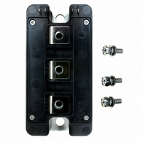
IGBT MOD DUAL 1200V 100A A SER
Manufacturer
Powerex Inc
Series
IGBTMOD™r
Type
IGBT Moduler
Datasheet
1.CM100DY-24A.pdf
(4 pages)
Specifications of CM100DY-24A
Configuration
Half Bridge
Voltage - Collector Emitter Breakdown (max)
1200V
Vce(on) (max) @ Vge, Ic
3V @ 15V, 100A
Current - Collector (ic) (max)
100A
Current - Collector Cutoff (max)
1mA
Input Capacitance (cies) @ Vce
17.5nF @ 10V
Power - Max
672W
Input
Standard
Ntc Thermistor
No
Mounting Type
Chassis Mount
Package / Case
Module
Transistor Polarity
N Channel
Dc Collector Current
100A
Collector Emitter Voltage Vces
1.2kV
Power Dissipation Pd
672W
Collector Emitter Voltage V(br)ceo
1.2kV
Prx Availability
RequestQuote
Distributorinventory
View
Voltage
1200V
Current
100A
Circuit Configuration
Dual
Rohs Compliant
Yes
Recommended Gate Driver
VLA504
Recommended Dc To Dc Converter
VLA106-15242 or VLA106-24242
Interface Circuit Ref Design
BG2B-3015
Lead Free Status / RoHS Status
Lead free / RoHS Compliant
For Use With
BG2B-5015 - KIT DEV BOARD 2CN 5A FOR IGBTBG2B-3015 - KIT DEV BOARD 2CN 3A FOR IGBTBG2B-1515 - KIT DEV BOARD 1.5A FOR IGBTBG2A-NF - KIT DEV BOARD FOR IGBT
Igbt Type
-
Lead Free Status / RoHS Status
Lead free / RoHS Compliant, Lead free / RoHS Compliant
Other names
835-1005
Available stocks
Company
Part Number
Manufacturer
Quantity
Price

Part Number:
CM100DY-24A
Manufacturer:
MITSUBISHI/三菱
Quantity:
20 000
Part Number:
CM100DY-24A
Quantity:
55


2
Powerex, Inc., 173 Pavilion Lane, Youngwood, Pennsylvania 15697 (724) 925-7272
CM100DY-24A
Dual IGBTMOD™ A-Series Module
100 Amperes/1200 Volts
Absolute Maximum Ratings, T j = 25°C unless otherwise specified
Ratings
Junction Temperature
Storage Temperature
Collector-Emitter Voltage (G-E Short)
Gate-Emitter Voltage (C-E Short)
Collector Current (DC, T C = 84°C*)
Peak Collector Current
Emitter Current*** (T C = 25°C)
Peak Emitter Current***
Maximum Collector Dissipation (T C = 25°C*, T j ≤ 150°C)
Mounting Torque, M5 Main Terminal
Mounting Torque, M6 Mounting
Weight
Isolation Voltage (Main Terminal to Baseplate, AC 1 min.)
Static Electrical Characteristics, T j = 25°C unless otherwise specified
Characteristics
Collector-Cutoff Current
Gate Leakage Current
Gate-Emitter Threshold Voltage
Collector-Emitter Saturation Voltage
Total Gate Charge
Emitter-Collector Voltage**
Dynamic Electrical Characteristics, T j = 25°C unless otherwise specified
Characteristics
Input Capacitance
Output Capacitance
Reverse Transfer Capacitance
Inductive
Load
Switch
Time
Diode Reverse Recovery Time***
Diode Reverse Recovery Charge***
*T C , T f measured point is just under the chips.
**Pulse width and repetition rate should be such that device junction temperature (T j ) does not exceed T j(max) rating.
***Represents characteristics of the anti-parallel, emitter-to-collector free-wheel diode (FWDi).
Turn-on Delay Time
Rise Time
Turn-off Delay Time
Fall Time
V CE(sat)
V GE(th)
Symbol
Symbol
t d(on)
t d(off)
I GES
I CES
C oes
C res
V EC
C ies
Q G
Q rr
t rr
t r
t f
V CC = 600V, I C = 100A, V GE = 15V
I C = 100A, V GE = 15V, T j = 125°C
V GE1 = V GE2 = 15V, R G = 3.1Ω,
I C = 100A, V GE = 15V, T j = 25°C
V CE = V CES , V GE = 0V
V GE = V GES , V CE = 0V
V CC = 600V, I C = 100A,
I C = 10mA, V CE = 10V
V CE = 10V, V GE = 0V
I E = 100A, V GE = 0V
Switching Operation,
Inductive Load
Test Conditions
Test Conditions
I E = 100A
Symbol
V CES
V GES
V ISO
T stg
I CM
I EM
P C
I C
I E
—
—
—
T j
Min.
Min.
6.0
—
—
—
—
—
—
—
—
—
—
—
—
—
—
—
CM100DY-24A
–40 to 150
–40 to 125
200**
200**
1200
2500
±20
100
100
672
310
30
40
Typ.
Typ.
500
7.0
2.1
2.4
5.0
—
—
—
—
—
—
—
—
—
—
—
Max.
Max.
100
400
350
150
1.0
0.5
8.0
3.0
3.8
—
—
—
17.5
70
1.5
0.34
Amperes
Amperes
Amperes
Amperes
Grams
Rev. 10/07
Watts
Volts
Volts
Volts
Units
in-lb
in-lb
°C
°C
Volts
Volts
Volts
Volts
Units
Units
mA
µA
nC
µC
ns
ns
ns
ns
ns
nf
nf
nf
Related parts for CM100DY-24A
Image
Part Number
Description
Manufacturer
Datasheet
Request
R

Part Number:
Description:
IGBT MOD DUAL 600V 100A H SER
Manufacturer:
Powerex Inc
Datasheet:
Part Number:
Description:
IGBT MOD DUAL 1200V 100A H SER
Manufacturer:
Powerex Inc
Datasheet:

Part Number:
Description:
IGBT MOD DUAL 1200V 100A NF SER
Manufacturer:
Powerex Inc
Datasheet:

Part Number:
Description:
SINGLE IGBTMOD(TM) TRANSISTOR MODULES DUAL IGBTMOD TRANSISTOR MODULES
Manufacturer:
Powerex Inc
Part Number:
Description:
IGBT MODULE A-SERIES DUAL DP 1700 100
Manufacturer:
Powerex Inc
Datasheet:
Part Number:
Description:
TRANSISTOR,IGBT POWER MODULE,HALF BRIDGE,1.4kV V(BR)CES,100A I(C)
Manufacturer:
Powerex Inc
Datasheet:


Part Number:
Description:
RF Devices / Rectifier Diodes
Manufacturer:
Bharat Electronics Ltd
Part Number:
Description:
Molded Mini-dyad
Manufacturer:
ETC-unknow
Datasheet:
Part Number:
Description:
Plug Connector
Manufacturer:
DDK Ltd.
Datasheet:
Part Number:
Description:
Molded Mini-DYAD
Manufacturer:
CLARE [Clare, Inc.]
Datasheet:
Part Number:
Description:
One-Touch Locking Style Small Sized Circular Connectors
Manufacturer:
DDK [DDK Ltd.]
Datasheet:

Part Number:
Description:
INDUCTOR CHIP SMD
Manufacturer:
Bourns Inc.
Datasheet:
Part Number:
Description:
INDUCTOR CHIP SMD
Manufacturer:
Bourns Inc.
Datasheet: