CM100DY-24A Powerex Inc, CM100DY-24A Datasheet - Page 4
CM100DY-24A
Manufacturer Part Number
CM100DY-24A
Description
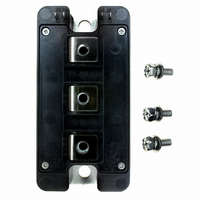
IGBT MOD DUAL 1200V 100A A SER
Manufacturer
Powerex Inc
Series
IGBTMOD™r
Type
IGBT Moduler
Datasheet
1.CM100DY-24A.pdf
(4 pages)
Specifications of CM100DY-24A
Configuration
Half Bridge
Voltage - Collector Emitter Breakdown (max)
1200V
Vce(on) (max) @ Vge, Ic
3V @ 15V, 100A
Current - Collector (ic) (max)
100A
Current - Collector Cutoff (max)
1mA
Input Capacitance (cies) @ Vce
17.5nF @ 10V
Power - Max
672W
Input
Standard
Ntc Thermistor
No
Mounting Type
Chassis Mount
Package / Case
Module
Transistor Polarity
N Channel
Dc Collector Current
100A
Collector Emitter Voltage Vces
1.2kV
Power Dissipation Pd
672W
Collector Emitter Voltage V(br)ceo
1.2kV
Prx Availability
RequestQuote
Distributorinventory
View
Voltage
1200V
Current
100A
Circuit Configuration
Dual
Rohs Compliant
Yes
Recommended Gate Driver
VLA504
Recommended Dc To Dc Converter
VLA106-15242 or VLA106-24242
Interface Circuit Ref Design
BG2B-3015
Lead Free Status / RoHS Status
Lead free / RoHS Compliant
For Use With
BG2B-5015 - KIT DEV BOARD 2CN 5A FOR IGBTBG2B-3015 - KIT DEV BOARD 2CN 3A FOR IGBTBG2B-1515 - KIT DEV BOARD 1.5A FOR IGBTBG2A-NF - KIT DEV BOARD FOR IGBT
Igbt Type
-
Lead Free Status / RoHS Status
Lead free / RoHS Compliant, Lead free / RoHS Compliant
Other names
835-1005
Available stocks
Company
Part Number
Manufacturer
Quantity
Price

Part Number:
CM100DY-24A
Manufacturer:
MITSUBISHI/三菱
Quantity:
20 000
Part Number:
CM100DY-24A
Quantity:
55


4
Powerex, Inc., 173 Pavilion Lane, Youngwood, Pennsylvania 15697 (724) 925-7272
CM100DY-24A
Dual IGBTMOD™ A-Series Module
100 Amperes/1200 Volts
10
10
10
10
10
10
10
10
10
10
-1
-2
-3
3
2
1
2
1
0
0
10
10
10
REVERSE RECOVERY CHARACTERISTICS
1
0
V
V
R
T
Inductive Load
-3
Single Pulse
T
Per Unit Base =
R
R
j
CC
GE
G
C
IMPEDANCE CHARACTERISTICS
th(j-c)
th(j-c)
= 25°C
0.186°C/W
(IGBT)
0.34°C/W
(FWDi)
= 3.1Ω
= 25°C
GATE RESISTANCE (TYPICAL)
= 600V
= 15V
EMITTER CURRENT, I
E
E
10
SW(on)
SW(off)
=
=
TRANSIENT THERMAL
GATE RESISTANCE, R
SWITCHING LOSS VS.
-2
(IGBT & FWDi)
(TYPICAL)
TIME, (s)
10
10
10
10
-1
-5
2
1
E
V
V
I
T
Inductive Load
C Snubber at Bus
C
, (AMPERES)
CC
GE
j
= 125°C
= 100A
G
= 600V
= 15V
, (Ω)
10
10
-4
0
I
t
rr
rr
10
10
10
10
3
-3
10
10
10
2
1
10
10
10
3
2
1
-1
-2
-3
10
10
10
20
16
12
8
4
0
2
1
0
REVERSE RECOVERY SWITCHING LOSS VS.
10
0
1
I
C
= 100A
EMITTER CURRENT, I
160
GATE CHARGE VS. V GE
GATE CHARGE, Q
EMITTER CURRENT
V
CC
320
(TYPICAL)
= 400V
10
2
480
V
V
R
T
Inductive Load
C Snubber at Bus
E
V
, (AMPERES)
CC
GE
j
G
G
= 125°C
CC
, (nC)
= 3.1Ω
= 600V
= 15V
= 600V
640
800
10
3
10
10
10
10
10
10
2
1
0
2
1
0
10
10
REVERSE RECOVERY SWITCHING LOSS VS.
-1
1
V
V
R
T
Inductive Load
C Snubber at Bus
V
V
I
T
Inductive Load
C Snubber at Bus
C
CC
GE
j
j
G
CC
GE
COLLECTOR CURRENT (TYPICAL)
= 125°C
= 100A
= 125°C
COLLECTOR CURRENT, I
= 3.1Ω
= 600V
= 15V
= 600V
= 15V
SWITCHING LOSS VS.
GATE RESISTANCE, R
GATE RESISTANCE
(TYPICAL)
10
10
2
0
C
, (AMPERES)
G
, ()
E
E
SW(on)
SW(off)
Rev. 10/07
10
10
3
1
Related parts for CM100DY-24A
Image
Part Number
Description
Manufacturer
Datasheet
Request
R

Part Number:
Description:
IGBT MOD DUAL 600V 100A H SER
Manufacturer:
Powerex Inc
Datasheet:
Part Number:
Description:
IGBT MOD DUAL 1200V 100A H SER
Manufacturer:
Powerex Inc
Datasheet:

Part Number:
Description:
IGBT MOD DUAL 1200V 100A NF SER
Manufacturer:
Powerex Inc
Datasheet:

Part Number:
Description:
SINGLE IGBTMOD(TM) TRANSISTOR MODULES DUAL IGBTMOD TRANSISTOR MODULES
Manufacturer:
Powerex Inc
Part Number:
Description:
IGBT MODULE A-SERIES DUAL DP 1700 100
Manufacturer:
Powerex Inc
Datasheet:
Part Number:
Description:
TRANSISTOR,IGBT POWER MODULE,HALF BRIDGE,1.4kV V(BR)CES,100A I(C)
Manufacturer:
Powerex Inc
Datasheet:


Part Number:
Description:
RF Devices / Rectifier Diodes
Manufacturer:
Bharat Electronics Ltd
Part Number:
Description:
Molded Mini-dyad
Manufacturer:
ETC-unknow
Datasheet:
Part Number:
Description:
Plug Connector
Manufacturer:
DDK Ltd.
Datasheet:
Part Number:
Description:
Molded Mini-DYAD
Manufacturer:
CLARE [Clare, Inc.]
Datasheet:
Part Number:
Description:
One-Touch Locking Style Small Sized Circular Connectors
Manufacturer:
DDK [DDK Ltd.]
Datasheet:

Part Number:
Description:
INDUCTOR CHIP SMD
Manufacturer:
Bourns Inc.
Datasheet:
Part Number:
Description:
INDUCTOR CHIP SMD
Manufacturer:
Bourns Inc.
Datasheet: