IXGN50N60BD2 IXYS, IXGN50N60BD2 Datasheet

IGBT 600V FRD SOT-227B

IXGN50N60BD2

Manufacturer Part Number
IXGN50N60BD2
Description
IGBT 600V FRD SOT-227B
Manufacturer
IXYS
Series
HiPerFAST™r
Datasheet

Specifications of IXGN50N60BD2

Configuration
Single
Voltage - Collector Emitter Breakdown (max)
600V
Vce(on) (max) @ Vge, Ic
2.5V @ 15V, 50A
Current - Collector (ic) (max)
75A
Current - Collector Cutoff (max)
200µA
Input Capacitance (cies) @ Vce
4.1nF @ 25V
Power - Max
250W
Input
Standard
Ntc Thermistor
No
Mounting Type
Chassis Mount
Package / Case
SOT-227, miniBLOC
Channel Type
N
Collector-emitter Voltage
600V
Collector Current (dc) (max)
75A
Gate To Emitter Voltage (max)
±20V
Mounting
Screw
Operating Temperature (min)
-40C
Operating Temperature (max)
150C
Operating Temperature Classification
Automotive
Lead Free Status / RoHS Status
Lead free / RoHS Compliant
Igbt Type
-
Lead Free Status / RoHS Status
Compliant, Lead free / RoHS Compliant

Available stocks

Company
Part Number
Manufacturer
Quantity
Price
Part Number:
IXGN50N60BD2
Manufacturer:
SAKEN
Quantity:
5 000
© 2000 IXYS All rights reserved
HiPerFAST
with HiPerFRED
Buck & boost configurations
Symbol
BV
V
I
I
V
IXYS reserves the right to change limits, test conditions, and dimensions.
CES
GES
GE(th)
CE(sat)
CES
SSOA
(RBSOA) Clamped inductive load, L = 30 mH
Maximum lead temperature for soldering
1.6 mm (0.062 in.) from case for 10 s
Symbol
V
V
V
V
I
I
I
P
V
I
I
P
T
T
T
M
Weight
CM
FRM
C25
C90
FAVM
RRM
J
JM
stg
CES
CGR
GES
GEM
C
D
d
Test Conditions
I
I
V
V
V
I
C
C
C
CE
GE
CE
= 250 mA, V
= 250 mA, V
= 0.8 • V
= 0 V
= 0 V, V
= I
Test Conditions
T
T
Continuous
Transient
T
T
T
V
T
T
t
T
Mounting torque
Terminal connection torque (M4)
P
J
J
C
C
C
C
C
C
C90
GE
z<10 ms; pulse width limited by T
= 25°C to 150°C
= 25°C to 150°C; R
= 25°C
= 90°C
= 25°C, 1 ms
= 25°C
= 70°C; rectangular, d = 50%
= 25°C
TM
= 15 V, T
, V
GE
GE
CES
IGBT
= 15 V
= ±20 V
GE
CE
VJ
= 0 V
= V
= 125°C, R
GE
GE
T
T
J
J
= 1 MW
(T
= 25°C
= 125°C
G
J
= 10 W
= 25°C, unless otherwise specified)
...BD2
IXGN 50N60BD2
IXGN 50N60BD3
J
min.
600
2.5
Characteristic Values
-40 ... +150
-40 ... +150
@ 0.8 V
Maximum Ratings
I
CM
typ.
1.5/13 Nm/lb.in.
1.5/13 Nm/lb.in.
= 100
600
600
600
±20
±30
200
250
600
150
150
300
CES
75
50
60
30
max.
±100
...BD3
200
2.5
5
1 mA
V
V
mA
nA
°C
°C
°C
°C
V
W
W
V
V
V
V
A
A
A
A
V
A
A
g
IXGN50N60BD2
1 = Emitter; 2 = Gate
3 = Collector; 4 = Diode cathode
IXGN50N60BD3
1 = Emitter/Diode Cathode; 2 = Gate
3 = Collector; 4 = Diode anode
Features
• International standard package
• Aluminium nitride isolation
• Isolation voltage 3000 V~
• Very high current, fast switching
• MOS Gate turn-on
• Low collector-to-case capacitance
• Low package inductance (< 10 nH)
• Molding epoxies meet UL 94 V-0
Applications
• AC motor speed control
• DC servo and robot drives
• DC choppers
• Buck converters
Advantages
• Easy to mount with 2 screws
• Space savings
• High power density
SOT-227B, miniBLOC
V
I
V
t
C25
fi
miniBLOC
- high power dissipation
IGBT & FRED diode
- drive simplicity
- easy to drive and to protect
flammability classification
CES
CE(sat)
E 153432
= 600 V
=
= 2.5 V
= 150 ns
2
75 A
1
98502C (8/99)
3
1 - 5
4

Related parts for IXGN50N60BD2

IXGN50N60BD2 Summary of contents

Page 1

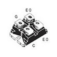
... CES I = C25 V = 2.5 V CE(sat 150 ns fi ...BD3 SOT-227B, miniBLOC E 153432 IXGN50N60BD2 Emitter Gate 3 = Collector Diode cathode A IXGN50N60BD3 Emitter/Diode Cathode Gate 3 = Collector Diode anode V A Features A • International standard package W miniBLOC °C • Aluminium nitride isolation - high power dissipation °C • Isolation voltage 3000 V~ ° ...

Page 2

... CES J 4.2 0.05 Characteristic Values (T = 25°C, unless otherwise specified) J typ 25° 25° IXYS MOSFETS and IGBTs are covered by one or more of the following U.S. patents: 4,835,592 4,881,106 5,017,508 4,850,072 4,931,844 5,034,796 IXGN 50N60BD2 IXGN 50N60BD3 miniBLOC, SOT-227 B max screws (4x) supplied nC Dim. ...

Page 3

... GE 13V 80 11V Volts CE Fig. 3. Saturation Voltage Characteristics 100 V = 10V 125° Volts GE Fig. 5. Saturation Voltage Characteristics © 2000 IXYS All rights reserved V = 15V GE 13V 11V 10000 T = 25° IXGN 50N60BD2 IXGN 50N60BD3 200 T = 25°C J 11V V = 15V GE 13V 160 120 80 40 ...

Page 4

... C Fig. 7. Dependence =50A 250V 100 150 Q - nanocoulombs g Fig. 9. Gate Charge 1 0.1 0.01 0.001 0.00001 0.0001 Fig. 11. Transient Thermal Resistance © 2000 IXYS All rights reserved (ON (OFF 100 and OFF C 600 100 0.1 200 250 300 0.001 Pulse Width - Seconds IXGN 50N60BD2 ...

Page 5

... T VJ Fig. 15 Dynamic parameters versus K/W 0.1 Z thJC 0.01 0.001 0.0001 0.00001 0.0001 0.001 Fig. 18 Transient thermal resistance junction to case © 2000 IXYS All rights reserved 4000 T = 100° 300V nC R 3000 I =120A 60A 30A F 2000 1000 0 m 100 ...

Related keywords