GA200SA60U Vishay, GA200SA60U Datasheet - Page 2
GA200SA60U
Manufacturer Part Number
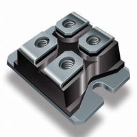
GA200SA60U
Description
IGBT UFAST 600V 100A SOT227
Manufacturer
Vishay
Specifications of GA200SA60U
Configuration
Single
Voltage - Collector Emitter Breakdown (max)
600V
Vce(on) (max) @ Vge, Ic
1.9V @ 15V, 100A
Current - Collector (ic) (max)
200A
Current - Collector Cutoff (max)
1mA
Input Capacitance (cies) @ Vce
16.5nF @ 30V
Power - Max
500W
Input
Standard
Ntc Thermistor
No
Mounting Type
Chassis Mount
Package / Case
SOT-227, miniBLOC
Lead Free Status / RoHS Status
Contains lead / RoHS non-compliant
Igbt Type
-
Lead Free Status / Rohs Status
Not Compliant
Other names
*GA200SA60U
VS-GA200SA60U
VS-GA200SA60U
VSGA200SA60U
VSGA200SA60U
VS-GA200SA60U
VS-GA200SA60U
VSGA200SA60U
VSGA200SA60U
Available stocks
Company
Part Number
Manufacturer
Quantity
Price
Company:

Part Number:
GA200SA60U
Manufacturer:
IR
Quantity:
1 000
Part Number:
GA200SA60U
Quantity:
62
Part Number:
GA200SA60UP
Quantity:
63
Company:
Part Number:
GA200SA60UPBF
Manufacturer:
AVX
Quantity:
25 000


GA200SA60U
Notes:
Q
R
S
Electrical Characteristics @ T
Switching Characteristics @ T
V
V
DV
V
V
∆V
g
I
I
Q
Q
Q
t
t
t
t
E
E
E
t
t
t
t
E
L
C
C
C
GES
CES
d(on)
d(off)
f
d(on)
d(off)
f
r
r
fe
E
(BR)CES
(BR)ECS
GE(th)
on
off
CE(ON)
ts
ts
oes
ies
res
g
ge
gc
2
(BR)CES
GE(th)
Repetitive rating; V
max. junction temperature. ( See fig. 13b )
V
(See fig. 13a)
Repetitive rating; pulse width limited by maximum
junction temperature.
CC
/∆T
/DT
= 80%(V
J
J
Parameter
Collector-to-Emitter Breakdown Voltage
Emitter-to-Collector Breakdown Voltage T
Temperature Coeff. of Breakdown Voltage
Collector-to-Emitter Saturation Voltage
Gate Threshold Voltage
Temperature Coeff. of Threshold Voltage
Forward Transconductance U
Zero Gate Voltage Collector Current
Gate-to-Emitter Leakage Current
Parameter
Total Gate Charge (turn-on)
Gate - Emitter Charge (turn-on)
Gate - Collector Charge (turn-on)
Turn-On Delay Time
Rise Time
Turn-Off Delay Time
Fall Time
Turn-On Switching Loss
Turn-Off Switching Loss
Total Switching Loss
Turn-On Delay Time
Rise Time
Turn-Off Delay Time
Fall Time
Total Switching Loss
Internal Emitter Inductance
Input Capacitance
Output Capacitance
Reverse Transfer Capacitance
CES
), V
GE
GE
= 20V, pulse width limited by
= 20V, L = 10µH, R
J
J
= 25°C (unless otherwise specified)
G
= 25°C (unless otherwise specified)
= 2.0Ω,
Min. Typ. Max. Units
Min. Typ. Max. Units
600
3.0
18
79
—
—
—
—
—
—
—
—
—
—
—
—
—
—
—
—
—
—
—
—
—
—
—
—
— 16500 —
—
—
T
U
1000
0.38
1.60
1.92
1.54
0.98
3.48
4.46
7.24
770 1200
100
260
130
300
160
460
200
-11
5.0
—
—
—
—
—
—
54
79
56
75
Pulse width ≤ 80µs; duty factor ≤ 0.1%.
Pulse width 5.0µs, single shot.
±250
150
380
200
450
1.9
6.0
1.0
7.6
—
—
—
—
—
—
—
10
—
—
—
—
—
—
—
—
—
—
—
—
mV/°C V
V/°C
mA
mJ
mJ
nA
nC
ns
nH
pF
ns
V
V
V
S
V
V
V
V
V
V
V
V
I
V
V
T
I
V
Energy losses include "tail"
See Fig. 9, 10, 14
T
I
V
Energy losses include "tail"
See Fig. 10, 11, 14
Measured 5mm from package
V
V
ƒ = 1.0MHz
I
I
I
C
C
C
C
C
C
GE
GE
GE
CE
CE
CE
GE
GE
GE
J
J
CC
GE
GE
GE
GE
CC
= 100A
= 100A, V
= 100A, V
= 100A
= 200A
= 100A , T
= 25°C
= 150°C,
= V
= V
= ±20V
= 0V, I
= 0V, I
= 0V, I
= 100V, I
= 0V, V
= 0V, V
= 15V
= 0V
= 400V
= 15V, R
= 15V, R
= 30V
GE
GE
Conditions
Conditions
, I
, I
C
C
C
CE
CE
C
C
= 250µA
= 1.0A
= 10 mA
CC
CC
J
= 250µA
= 2.0 mA
C
G
G
= 600V
= 600V, T
= 150°C
= 100A
= 2.0Ω
= 2.0Ω
= 480V
= 480V
See Fig. 8
See Fig. 7
www.irf.com
J
V
See Fig.2, 5
= 150°C
GE
= 15V
Related parts for GA200SA60U
Image
Part Number
Description
Manufacturer
Datasheet
Request
R

Part Number:
Description:
Power Inductors 223uH Power Inductor
Manufacturer:
Gowanda Electronics
Datasheet:
Part Number:
Description:
Power Inductors 100uH 0.208ohms 1.2A
Manufacturer:
Gowanda Electronics
Datasheet:


Part Number:
Description:
357-036-542-201 CARDEDGE 36POS DL .156 BLK LOPRO
Manufacturer:
Vishay
Datasheet:
Part Number:
Description:
357-036-542-201 CARDEDGE 36POS DL .156 BLK LOPRO
Manufacturer:
Vishay
Datasheet:
Part Number:
Description:
357-036-542-201 CARDEDGE 36POS DL .156 BLK LOPRO
Manufacturer:
Vishay
Datasheet:
Part Number:
Description:
357-036-542-201 CARDEDGE 36POS DL .156 BLK LOPRO
Manufacturer:
Vishay
Datasheet:
Part Number:
Description:
357-036-542-201 CARDEDGE 36POS DL .156 BLK LOPRO
Manufacturer:
Vishay
Datasheet:
Part Number:
Description:
357-036-542-201 CARDEDGE 36POS DL .156 BLK LOPRO
Manufacturer:
Vishay
Datasheet:
Part Number:
Description:
357-036-542-201 CARDEDGE 36POS DL .156 BLK LOPRO
Manufacturer:
Vishay
Datasheet:
Part Number:
Description:
357-036-542-201 CARDEDGE 36POS DL .156 BLK LOPRO
Manufacturer:
Vishay
Datasheet:
Part Number:
Description:
357-036-542-201 CARDEDGE 36POS DL .156 BLK LOPRO
Manufacturer:
Vishay
Datasheet:
Part Number:
Description:
357-036-542-201 CARDEDGE 36POS DL .156 BLK LOPRO
Manufacturer:
Vishay
Datasheet:
Part Number:
Description:
357-036-542-201 CARDEDGE 36POS DL .156 BLK LOPRO
Manufacturer:
Vishay
Datasheet:
Part Number:
Description:
357-036-542-201 CARDEDGE 36POS DL .156 BLK LOPRO
Manufacturer:
Vishay
Datasheet: