GA200SA60U Vishay, GA200SA60U Datasheet - Page 3
GA200SA60U
Manufacturer Part Number
GA200SA60U
Description
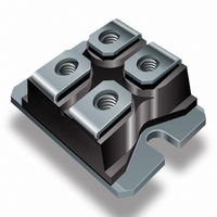
IGBT UFAST 600V 100A SOT227
Manufacturer
Vishay
Specifications of GA200SA60U
Configuration
Single
Voltage - Collector Emitter Breakdown (max)
600V
Vce(on) (max) @ Vge, Ic
1.9V @ 15V, 100A
Current - Collector (ic) (max)
200A
Current - Collector Cutoff (max)
1mA
Input Capacitance (cies) @ Vce
16.5nF @ 30V
Power - Max
500W
Input
Standard
Ntc Thermistor
No
Mounting Type
Chassis Mount
Package / Case
SOT-227, miniBLOC
Lead Free Status / RoHS Status
Contains lead / RoHS non-compliant
Igbt Type
-
Lead Free Status / Rohs Status
Not Compliant
Other names
*GA200SA60U
VS-GA200SA60U
VS-GA200SA60U
VSGA200SA60U
VSGA200SA60U
VS-GA200SA60U
VS-GA200SA60U
VSGA200SA60U
VSGA200SA60U
Available stocks
Company
Part Number
Manufacturer
Quantity
Price
Company:

Part Number:
GA200SA60U
Manufacturer:
IR
Quantity:
1 000
Part Number:
GA200SA60U
Quantity:
62
Part Number:
GA200SA60UP
Quantity:
63
Company:
Part Number:
GA200SA60UPBF
Manufacturer:
AVX
Quantity:
25 000


www.irf.com
1000
100
10
2 0 0
1 6 0
1 2 0
8 0
4 0
0
0.5
0.1
T = 150 C
J
Fig. 2 - Typical Output Characteristics
Square wave:
1.0
V
CE
°
60% of rated
, Collector-to-Emitter Voltage (V)
Ideal diodes
T = 25 C
voltage
1.5
J
°
2.0
Fig. 1 - Typical Load Current vs. Frequency
V
20µs PULSE WIDTH
GE
2.5
= 15V
(Load Current = I
1
3.0
3.5
f, Fre quen cy (kH z)
RMS
1000
of fundamental)
100
10
Fig. 3 - Typical Transfer Characteristics
5.0
For both:
Duty cycle: 50%
T = 125°C
T
Gate drive as specified
Power Dissipation = 140W
J
sink
= 90°C
V
T = 150 C
J
GE
1 0
, Gate-to-Emitter Voltage (V)
GA200SA60U
6.0
°
T = 25 C
J
Triangular wave:
°
V
20µs PULSE WIDTH
5µs PULSE WIDTH
CE
7.0
Clamp voltage:
80% of rated
= 25V
3
8.0
1 0 0
A
Related parts for GA200SA60U
Image
Part Number
Description
Manufacturer
Datasheet
Request
R

Part Number:
Description:
Power Inductors 223uH Power Inductor
Manufacturer:
Gowanda Electronics
Datasheet:
Part Number:
Description:
Power Inductors 100uH 0.208ohms 1.2A
Manufacturer:
Gowanda Electronics
Datasheet:


Part Number:
Description:
357-036-542-201 CARDEDGE 36POS DL .156 BLK LOPRO
Manufacturer:
Vishay
Datasheet:
Part Number:
Description:
357-036-542-201 CARDEDGE 36POS DL .156 BLK LOPRO
Manufacturer:
Vishay
Datasheet:
Part Number:
Description:
357-036-542-201 CARDEDGE 36POS DL .156 BLK LOPRO
Manufacturer:
Vishay
Datasheet:
Part Number:
Description:
357-036-542-201 CARDEDGE 36POS DL .156 BLK LOPRO
Manufacturer:
Vishay
Datasheet:
Part Number:
Description:
357-036-542-201 CARDEDGE 36POS DL .156 BLK LOPRO
Manufacturer:
Vishay
Datasheet:
Part Number:
Description:
357-036-542-201 CARDEDGE 36POS DL .156 BLK LOPRO
Manufacturer:
Vishay
Datasheet:
Part Number:
Description:
357-036-542-201 CARDEDGE 36POS DL .156 BLK LOPRO
Manufacturer:
Vishay
Datasheet:
Part Number:
Description:
357-036-542-201 CARDEDGE 36POS DL .156 BLK LOPRO
Manufacturer:
Vishay
Datasheet:
Part Number:
Description:
357-036-542-201 CARDEDGE 36POS DL .156 BLK LOPRO
Manufacturer:
Vishay
Datasheet:
Part Number:
Description:
357-036-542-201 CARDEDGE 36POS DL .156 BLK LOPRO
Manufacturer:
Vishay
Datasheet:
Part Number:
Description:
357-036-542-201 CARDEDGE 36POS DL .156 BLK LOPRO
Manufacturer:
Vishay
Datasheet:
Part Number:
Description:
357-036-542-201 CARDEDGE 36POS DL .156 BLK LOPRO
Manufacturer:
Vishay
Datasheet: