STE250NS10 STMicroelectronics, STE250NS10 Datasheet
STE250NS10
Specifications of STE250NS10
Available stocks


Related parts for STE250NS10


STE250NS10 Summary of contents
Page 1
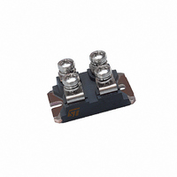
... Switching application Table 1. Device summary Order code STE250NS10 March 2010 N-channel 100 V, 0.0045 Ω , 220 A, ISOTOP STripFET™ Power MOSFET R I DS(on) D <0.0055 Ω 220 A Figure 1. Marking Package E250NS10 ISOTOP Doc ID 8220 Rev 3 STE250NS10 ISOTOP Internal schematic diagram Packaging Tube www.st.com 1/14 14 ...
Page 2
... Contents Contents 1 Electrical ratings . . . . . . . . . . . . . . . . . . . . . . . . . . . . . . . . . . . . . . . . . . . . 3 2 Electrical characteristics . . . . . . . . . . . . . . . . . . . . . . . . . . . . . . . . . . . . . 4 2.1 Electrical characteristics (curves) 3 Test circuits 4 Package mechanical data . . . . . . . . . . . . . . . . . . . . . . . . . . . . . . . . . . . . . 9 5 Mounting information . . . . . . . . . . . . . . . . . . . . . . . . . . . . . . . . . . . . . . . 11 5.1 Mounting on heatsink . . . . . . . . . . . . . . . . . . . . . . . . . . . . . . . . . . . . . . . . 11 6 Revision history . . . . . . . . . . . . . . . . . . . . . . . . . . . . . . . . . . . . . . . . . . . 13 2/ Doc ID 8220 Rev 3 STE250NS10 . . . . . . . . . . . . . . . . . . . . . . . . . . . . 6 ...
Page 3
... STE250NS10 1 Electrical ratings Table 2. Absolute maximum ratings Symbol V Drain-source voltage ( Gate- source voltage GS I Drain current (continuos Drain current (continuos (1) I Drain current (pulsed Total dissipation at T TOT Derating factor (2) dv/dt Peak diode recovery voltage slope V Insulation winthstand voltage (DC) ISO T Operating junction temperature ...
Page 4
... MHz Parameter Test conditions V = =4.7 Ω Figure (see V = =4.7 Ω Figure (see V = =4.7 Ω Figure (see Doc ID 8220 Rev 3 STE250NS10 Min. Typ 100 GS = 250 µ 125 A 0.0045 0.0055 D Min. Typ. Max 4.3 - 1.2 900 = 160 330 Min. Typ. =125 A, D 110 = ...
Page 5
... STE250NS10 Table 8. Source drain diode Symbol I Source-drain current SD (1) I Source-drain current (pulsed) SDM (2) V Forward on voltage SD t Reverse recovery time rr Q Reverse recovery charge rr I Reverse recovery current RRM 1. Pulse width limited by safe operating area. 2. Pulsed: Pulse duration = 300 µs, duty cycle 1.5 % ...
Page 6
... Electrical characteristics 2.1 Electrical characteristics (curves) Figure 2. Safe operating area Figure 4. Output characterisics Figure 6. Transconductance 6/14 Figure 3. Thermal impedance Figure 5. Transfer characteristics Figure 7. Static drain-source on resistance Doc ID 8220 Rev 3 STE250NS10 ...
Page 7
... STE250NS10 Figure 8. Gate charge vs gate-source voltage Figure 9. Figure 10. Normalized gate threshold voltage vs temperature Figure 12. Source-drain diode forward characteristics Capacitance variations Figure 11. Normalized on resistance vs temperature Figure 13. Normalized breakdown voltage vs temperature Doc ID 8220 Rev 3 Electrical characteristics 7/14 ...
Page 8
... Figure 14. Switching times test circuit for resistive load Figure 16. Test circuit for inductive load switching and diode recovery times Figure 18. Unclamped inductive waveform 8/14 Figure 15. Gate charge test circuit Figure 17. Unclamped inductive load test circuit Figure 19. Switching time waveform Doc ID 8220 Rev 3 STE250NS10 ...
Page 9
... STE250NS10 4 Package mechanical data In order to meet environmental requirements, ST offers these devices in different grades of ® ECOPACK packages, depending on their level of environmental compliance. ECOPACK specifications, grade definitions and product status are available at: www.st.com. ECOPACK trademark. Doc ID 8220 Rev 3 Package mechanical data ® 9/14 ...
Page 10
... Doc ID 8220 Rev 3 STE250NS10 inch MIN. TYP. MAX. 0.466 0.480 0.350 0.358 0.076 0.080 0.029 0.033 0.496 0.503 0.990 1.003 1.240 1.248 0.157 0.161 0.169 0.586 0.594 1 ...
Page 11
... STE250NS10 5 Mounting information 5.1 Mounting on heatsink Figure 20. Screws distance Table 9. Heatsink specification (max concavity or convexity between fixing holes) Surface finish Table 10. Mounting specification R Table 11. Connectors Parameter Flatness Fixing holes Parameter Fixing screw Torque thj-case/heatsink Parameter Screws Torque Pull test (fast on pins) ...
Page 12
... Contact area (screw version) Lead inductance Figure 21. Mounting section Figure 22. Cross form Table 12. Package for shipment Shipment Elementary box (bulk quantity) Ordered quantity 12/14 Parameter Tube Doc ID 8220 Rev 3 STE250NS10 Value ≤ Details 10 pcs + contact set (screw +washer) 100 pieces (10 tubes) Multiples of 10 pcs ...
Page 13
... STE250NS10 6 Revision history Table 13. Revision history Date 21-Jun-2004 04-Oct-2006 22-Mar-2010 Revision 1 Complete version. 2 New template, no content change. Section 5: Mounting 3 Added Doc ID 8220 Rev 3 Revision history Changes information. 13/14 ...
Page 14
... Australia - Belgium - Brazil - Canada - China - Czech Republic - Finland - France - Germany - Hong Kong - India - Israel - Italy - Japan - Malaysia - Malta - Morocco - Philippines - Singapore - Spain - Sweden - Switzerland - United Kingdom - United States of America 14/14 Please Read Carefully: © 2010 STMicroelectronics - All rights reserved STMicroelectronics group of companies www.st.com Doc ID 8220 Rev 3 STE250NS10 ...