FSAM30SH60A Fairchild Semiconductor, FSAM30SH60A Datasheet - Page 13
FSAM30SH60A
Manufacturer Part Number
FSAM30SH60A
Description
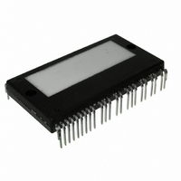
SMART POWER MODULE 30A SPM32-AA
Manufacturer
Fairchild Semiconductor
Series
SPM™r
Type
IGBTr
Datasheet
1.FSAM30SH60A.pdf
(16 pages)
Specifications of FSAM30SH60A
Configuration
3 Phase
Current
30A
Voltage
600V
Voltage - Isolation
2500Vrms
Package / Case
SPM32AA
Collector- Emitter Voltage Vceo Max
600 V
Collector-emitter Saturation Voltage
2.5 V
Continuous Collector Current At 25 C
30 A
Gate-emitter Leakage Current
62 W
Power Dissipation
62 W
Mounting Style
SMD/SMT
Operating Temperature (max)
125C
Operating Temperature (min)
-20C
Pin Count
32
Mounting
Through Hole
Package Type
SPM32-AA
Case Length
60mm
Case Height
7.2mm
Screening Level
Commercial
Lead Free Status / RoHS Status
Lead free / RoHS Compliant
Other names
FSAM30SH60A_NL
FSAM30SH60A_NL
FSAM30SH60A_NL
Available stocks
Company
Part Number
Manufacturer
Quantity
Price
Company:

Part Number:
FSAM30SH60A
Manufacturer:
FAIRCHILD
Quantity:
27
Company:
Part Number:
FSAM30SH60A
Manufacturer:
VICOR
Quantity:
300


©2003 Fairchild Semiconductor Corporation
Note:
1) It would be recommended that by-pass capacitors for the gating input signals, IN
2) The logic input is compatible with standard CMOS or LSTTL outputs.
3) R
Note:
It would be recommended that the bootstrap diode, D
and on the both sides of CPU and SPM for the fault output signal, V
each of SPM pins.
PL
C
PL
CPU
/R
470uF
PH
C
PH
/R
15V-Line
PF
C
PF
Fig. 14. Recommended Bootstrap Operation Circuit and Parameters
coupling at each SPM input is recommended in order to prevent input/output signals’ oscillation and it should be as close as possible to
These Values depend on PW M C ontrol Algorithm
20
Ω
1nF
Fig. 13. Recommended CPU I/O Interface Circuit
0.1uF
100
100
100
D
47uF
B S
Ω
Ω
Ω
BS
, has soft and fast recovery characteristics.
4.7k
R
C
1nF
P F
P F
0.1uF
Ω
FO
, as close as possible.
0.47nF
C
2k
R
P L
One-Leg Diagram of SPM
(UL)
P L
Ω
, IN
5V-Line
IN
IN
COM
COM
Vcc
Vcc
(VL)
, IN
OUT
HO
VB
VS
(WL)
4.7k
1.2nF
R
C
P H
P H
, IN
Ω
(UH)
, IN
(VH)
and IN
CO M
IN
IN
V
FO
(UH)
(WH)
(UL)
P
N
,
,
should be placed on the SPM pins
IN
IN
Inverter
Output
(VH)
(VL)
SPM
,
,
IN
IN
(WH)
(WL)
Rev. E, August 2003
Related parts for FSAM30SH60A
Image
Part Number
Description
Manufacturer
Datasheet
Request
R

Part Number:
Description:
Fairchild Semiconductor [IGBT MODULE]
Manufacturer:
Fairchild Semiconductor
Datasheet:

Part Number:
Description:
Discrete Semiconductor Modules
Manufacturer:
Fairchild Semiconductor
Part Number:
Description:
Discrete Semiconductor Modules
Manufacturer:
Fairchild Semiconductor
Part Number:
Description:
This N-Channel MOSFET is produced using Fairchild Semiconductor’s advanced Power Trench® process
Manufacturer:
Fairchild Semiconductor
Datasheet:
Part Number:
Description:
This N-Channel MOSFET is produced using Fairchild Semiconductor’s advanced Power Trench® process
Manufacturer:
Fairchild Semiconductor
Datasheet:
Part Number:
Description:
This N-Channel MOSFET is produced using Fairchild Semiconductor’s advanced PowerTrench® process
Manufacturer:
Fairchild Semiconductor
Datasheet:
Part Number:
Description:
This N-Channel MOSFET is produced using Fairchild Semiconductor’s advanced PowerTrench® process
Manufacturer:
Fairchild Semiconductor
Datasheet:
Part Number:
Description:
This N-Channel MOSFET is produced using Fairchild Semiconductor’s advanced Power Trench® process
Manufacturer:
Fairchild Semiconductor
Datasheet:
Part Number:
Description:
This N-Channel logic Level MOSFETs are produced using Fairchild Semiconductor‘s advanced Power Trench® process that has been special tailored to minimize the on-state resistance and yet maintain superior switching performance
Manufacturer:
Fairchild Semiconductor
Datasheet:
Part Number:
Description:
This N-Channel MOSFET is produced using Fairchild Semiconductor’s advanced Power Trench® process
Manufacturer:
Fairchild Semiconductor
Datasheet:
Part Number:
Description:
This N-Channel SyncFET™ is produced using Fairchild Semiconductor’s advanced PowerTrench® process
Manufacturer:
Fairchild Semiconductor
Datasheet:
Part Number:
Description:
This N-Channel SyncFET™ is produced using Fairchild Semiconductor’s advanced PowerTrench® process
Manufacturer:
Fairchild Semiconductor
Datasheet:
Part Number:
Description:
This N-Channel SyncFET™ is produced using Fairchild Semiconductor’s advanced PowerTrench® process
Manufacturer:
Fairchild Semiconductor
Datasheet:
Part Number:
Description:
This N-Channel logic Level MOSFETs are produced using Fairchild Semiconductor‘s advanced Power Trench® process that has been special tailored to minimize the on-state resistance and yet maintain superior switching performance
Manufacturer:
Fairchild Semiconductor
Datasheet:
Part Number:
Description:
This N-Channel MOSFET is produced using Fairchild Semiconductor’s advanced Power Trench® process that has been especially tailored to minimize the on-state resistance and yet maintain superior switching performance
Manufacturer:
Fairchild Semiconductor
Datasheet: